diy solar

diy solar

Renogy DC DC Charger w/ MPPT

View attachment 1841

I love it so much, that I created a new solar power package on my website! Dead simple blueprint:

Click here for parts list and schematics

Pardon my newb question as I'm reviewing threads as they come up with active dialog. This intrigued me as I had considered the use of an alternator in my off-grid system, and while reviewing your one-line and project references I read this:

"Because this blueprint requires so many solar panels in parallel, adding a inline mc4 fuse is very smart to do."

Can you explain the rationale behind this per-panel fusing statement? Most all the panels I've looked at have integral blocking diodes, so I'm wondering if there another mode of failure this can account for that's not readily apparent to me?

Thanks in advance!
When panels are in Parallel, the Voltage remains the same. The amperage increases with every panel. Two 5A panels is 10A, four 5A panels is 20A.
High voltage at milliamps is not that dangerous. High Amperage at millivolts is more dangerous. Combine the two and the danger goes up real fast.
Most times you see a Danger High Voltage sign, there is high amperage present, too.
 
26 amp at 12v, and it does have charging profiles for various types of batteries. I wanted to go this round because I didn't want permanently put a AC charger in the van. I plan to move this charger around a bit.

......................

This is the thing that confuses me (not intuitive to me), because if the I put the ac charger on the solar input of the DC/DC-MMPT, there is one central charger that manages all inputs for both batteries(which makes sense to me).

However, if I throw in a AC charger separately, there are two separate charge controllers, I have to hope that the DC/DC-MPPT won't blow up and be ok with the AC charger's input coming in to the battery.

Sorry, I am bit dense. Thanks!

-Leave the solar input to the DCC50S for solar term points alone.
-Put the charger on the starter battery, or on the DCC50S starter battery input, or on the aux battery.
-I would suggest the starter battery. Select a charging voltage profile for the starter battery. This will charge the starter battery, aux battery and allow for concurrent solar charge of the aux battery if the panels are in the sun.
 
When panels are in Parallel, the Voltage remains the same. The amperage increases with every panel. Two 5A panels is 10A, four 5A panels is 20A.
High voltage at milliamps is not that dangerous. High Amperage at millivolts is more dangerous. Combine the two and the danger goes up real fast.
Most times you see a Danger High Voltage sign, there is high amperage present, too.

Thanks for answering. I'm a EE/Software engineer by trade and I get the power realtionships. I also concur with the notion of having fusing protection and was asking in context of "per panel" vs."per parallel panels" fusing convention. I'll be running multiple (3) x 100W HQST 12V mono panels in parallel to an Electrodacus DSSR20 and planned to fuse 30A downstream of the parallel tie-point for each SSR instance (hence my curiosity here and motivation for asking).

Because the aforementioned system is targeted for rooftop RV, it's likely easier to fuse inline individually with these MC4 interposed fuse holders than downstream and inline of the branch adapters.
Well 12V @ 100W is 8.33A and three would be over the 20A MC4 UL rating.
But 12V panels really put out more volts than that, so it changes the equation and amperage output.
Increase the voltage to 19V or 24V @ 100W and the amperage goes down at each step. E=IR & P=IE.....
 
Well 12V @ 100W is 8.33A and three would be over the 20A MC4 UL rating.
But 12V panels really put out more volts than that, so it changes the equation and amperage output.
Increase the voltage to 19V or 24V @ 100W and the amperage goes down at each step. E=IR & P=IE.....

Thanks @Sgt Raven, and true to all of this, however, the per-panel inline fuse doesn't change any of the power paradigms...
Which brings me full circle to the original Q, what were the motivating factors that underpinned the statement:

"Because this blueprint requires so many solar panels in parallel, adding a inline mc4 fuse is very smart to do."

If it's best practice to do this, then inquiring minds want to know.
It's really an @Will Prowse question since it's his website.
Yeah, I don't have the answer so I took a SWAG at it.

I saw a thing the other day, I wish I had known years ago.
With a test that has Ohm's Law as part
When you sit down, draw a T and put E or P on top. The put IR or IE in the two other spots.
Cover the one you need to find and the Formula is right in front of you.
When your brain turns to mush, you don't have to remember how to find the answer.

It would have made my Ham License test so much easier.

In High School I was studying Algebra in one class and doing Trig problems in my basic electronics class.
I didn't need to know how the formulas worked, to plug the known numbers in, do the math, and find the answer.
 
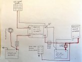
Just an FIY on this Renogy DC-DC MPPT charger. Maybe someone else with this can confirm as well. I have this installed in a small van application. I've attached a basic wiring diagram showing how I have this connected.

Recently, I had switched the house battery to the off position while I was doing some work to the vehicle. As I was moving the van around in my driveway, I noticed that my fridge, which is connected to the house fuse panel, was running...even though the house battery was switched off.

When I shut the van off, the fridge lost power and shut off as well. I started the van again, the fridge was off, but after a few seconds, the charger energized the positive side of the house circuit again.

Just to be sure, I completely disconnected the house battery by removing both the positive and negative leads from the battery and it made no difference, the house circuits were energized with the engine running.

This is a problem for obvious reasons, for one, if the inverter was switched on, it would be trying to draw high amps through the undersized wire from the charger and likely blow the 65 amp breaker or the renogy charger will automatically shut down. Either way, that's not ideal. Also, I don't want my house circuits to be energized when the battery switch is turned off, that's the whole point.

I contacted Renogy customer support and they told me that as far as they knew, the charger should not energize the positive lead on the charge side if it wasn't connected to a battery but the person I talked to wasn't sure.

Right now, I'm probably going to install a dual circuit battery switch in place of the single circuit switch that is there now and run the charge lead through one of the two switch circuits so there is no way for the charger to be connected to the house circuits.

Please let me knowimage0.jpeg what you think.
 

Attachments

  • image0.jpeg
    image0.jpeg
    61.7 KB · Views: 7
Seems to me that the only way you could be powering the fridge is if the Renogy is supplying it with power from the alternator ... Maybe a 2 pole disconnect switch that removes power out of the Renogy.
As an alternative, you could put a manual switch in the vehicle that would disconnect alternator power from the Renogy .... but that wouldn't guarantee that the PV side could still send thru some power.
I personally would probably have a disconnect on the Alternator and the PV power into the Renogy ... but not sure if that is best practice.
 
I cannot say for sure about the Renogy but I know a number of the all in one controllers will route power to the loads once the house battery is full. This is designed so if you have excess power available, it can power the loads without using any battery power. At least this is what I have read.

My understanding is you need to have a disconnect between all of your loads and any power source. In your diagram, I would move the + side off the Renogy to the + side of the battery and then a load wire off the battery, through your cutoff switch and then to all of the loads. This way there is never any way for any power source to reach the loads if the switch is turned off. As you have it wired now, your inverter is always connected to a power source and your fuse block is managed by the disconnect switch.
 
I don't about this unit, it may be OK because the starting battery is in the circuit.
But normally they say don't connect your PV panels to a SCC without the battery connected first.
 
I cannot say for sure about the Renogy but I know a number of the all in one controllers will route power to the loads once the house battery is full. This is designed so if you have excess power available, it can power the loads without using any battery power. At least this is what I have read.

My understanding is you need to have a disconnect between all of your loads and any power source. In your diagram, I would move the + side off the Renogy to the + side of the battery and then a load wire off the battery, through your cutoff switch and then to all of the loads. This way there is never any way for any power source to reach the loads if the switch is turned off. As you have it wired now, your inverter is always connected to a power source and your fuse block is managed by the disconnect switch.
I agree, but in my testing, I removed the battery completely and it still routed power. From my understanding, the renogy isn't even supposed to turn on without connection to the house battery but it's turning on with the alternator power instead. The reason I've attached the + side of the renogy to the other side of the switch is so I can manually control when the battery receives a charge.
 
Last edited:
Seems to me that the only way you could be powering the fridge is if the Renogy is supplying it with power from the alternator ... Maybe a 2 pole disconnect switch that removes power out of the Renogy.
As an alternative, you could put a manual switch in the vehicle that would disconnect alternator power from the Renogy .... but that wouldn't guarantee that the PV side could still send thru some power.
I personally would probably have a disconnect on the Alternator and the PV power into the Renogy ... but not sure if that is best practice.
My tentative plan is to install a 2 pole switch as you describe, one circuit for the battery positive and the other for the power out of the renogy. The renogy tech agreed that would be a solution. I'm still researching if this is best practice. I don't want to cause damage to the unit if solar panels were connected without the battery connection. Right now the van is in the garage and the solar panels are shut off at the solar breaker box (not shown in diagram).
 
I don't about this unit, it may be OK because the starting battery is in the circuit.
But normally they say don't connect your PV panels to a SCC without the battery connected first.
Thanks, I agree. I'm looking into this. As it is, the house battery is LiFePo which shouldn't be trickle charged, so I'm not sure how the charging profile deals with solar input once the house battery is charged, my guess is that the connection to the starting battery takes care of it as you mentioned. My tentative plan was to install a dual circuit battery switch so I can cut power out from the renogy to the positive side of the house circuit in addition to the battery disconnect, but I want to run it by renogy again to make sure.
 
The problem I am seeing in your diagram is the cutoff switch is between the battery and the SCC which still allows a direct path from the SCC to the inverter and fuse block (red arrow). Since the fridge is trying to use power, the SCC likely cannot tell the difference between a battery and your fridge (or any constant load). Even with the battery disconnected from the circuit, the fridge is acting like a battery as it is asking for power from the SCC, hence why the alt is passing power through, because it senses a load. Remember, these units are dumb. The don't know any difference between a battery needing charging or a load pulling power. It just sense a draw and power is routed through from any charge source (alt and/or solar).

What you need to do is to move your cutoff switch to the line BEFORE the battery and load connections (the blue arrow). This effectively cuts off any battery draw or load draw from the SCC so it can never sense there is a draw being pulled and hence, turning on one of the charge circuits from the SCC.

1590160977423.png
 
I think you should:
-Keep the House battery main disconnect as is on your wiring diagram and add a battery main fuse (class T fuse) in series with it.
-Add two more branch circuit switches/fuses/circuit breakers to your wiring,
one for the load center circuit (blue sea house fuse block) and
one for the inverter circuit
(especially if there is a difference in wire gauge for either/both of these circuits and the wire from house B+).
-Add a starter battery switch in series with the fuse you have there, close to the start battery.
-Read the DCC50S Installation, Connect the Battery directions again.
Renogy is very specific about the order that the power supplies and house battery are connected to the device,
As are most other MPPT charge controller manufacturers.
That's how mines wired, I don't get any unexpected feedback from the DCC50S device, I can isolate the solar panels, start battery and house battery from the device. (Please note that the house battery is always the first device connected to the device, and the last device disconnected from the device, before disconnecting the house battery or solar).
You also might choose to wire the Battery - terminal to the chassis ground, wire the DCC50S device - terminal to the battery -, and provide a B- wire from the battery to the load center - .

If you want comment on your fuse sizing, include the wire gauge and approx length of each wire in your diagram.
 
Last edited:
I think you should:
-Keep the House battery main disconnect as is on your wiring diagram and add a battery main fuse (class T fuse) in series with it.
-Add two more branch circuit switches/fuses/circuit breakers to your wiring,
one for the load center circuit (blue sea house fuse block) and
one for the inverter circuit
(especially if there is a difference in wire gauge for either/both of these circuits and the wire from house B+).
-Add a starter battery switch in series with the fuse you have there, close to the start battery.
-Read the DCC50S Installation, Connect the Battery directions again.
Renogy is very specific about the order that the power supplies and house battery are connected to the device,
As are most other MPPT charge controller manufacturers.
That's how mines wired, I don't get any unexpected feedback from the DCC50S device, I can isolate the solar panels, start battery and house battery from the device. (Please note that the house battery is always the first device connected to the device, and the last device disconnected from the device, before disconnecting the house battery or solar).
You also might choose to wire the Battery - terminal to the chassis ground, wire the DCC50S device - terminal to the battery -, and provide a B- wire from the battery to the load center - .

If you want comment on your fuse sizing, include the wire gauge and approx length of each wire in your diagram.
Thanks Randy, All the fuses, switches, and wires you mentioned are there, I just didn't include them in this diagram. I tried to keep it simple for the purpose of the discussion. I agree, I need to be more aware of the order I disconnect and connect.
 
Last edited:
The problem I am seeing in your diagram is the cutoff switch is between the battery and the SCC which still allows a direct path from the SCC to the inverter and fuse block (red arrow). Since the fridge is trying to use power, the SCC likely cannot tell the difference between a battery and your fridge (or any constant load). Even with the battery disconnected from the circuit, the fridge is acting like a battery as it is asking for power from the SCC, hence why the alt is passing power through, because it senses a load. Remember, these units are dumb. The don't know any difference between a battery needing charging or a load pulling power. It just sense a draw and power is routed through from any charge source (alt and/or solar).

What you need to do is to move your cutoff switch to the line BEFORE the battery and load connections (the blue arrow). This effectively cuts off any battery draw or load draw from the SCC so it can never sense there is a draw being pulled and hence, turning on one of the charge circuits from the SCC.

View attachment 13698
Thanks Chevy Mike. This is the simplest solution. I think I'm going to use a dual circuit switch so I can cut the line from the charger (your blue arrow) and the main positive from the battery to all loads concurrently. I want an easy to reach switch right on the battery box to cut it all at once. There are fuses to all the loads immediately after the battery switch and other switches for each load further down the line but I didn't diagram them here.
 
My 1st Camper Van (help please), (320 Watt solar panel)

In this Video tutorial...


Will uses this solar charge controller which is £199...

When there are solar charge controllers out there like this for £69.99...


My question is if there are cheaper options like the one below for £69.99, why go so expensive? Or is there a performance aspect i am missing?
 
Use a Renogy DCC50S, the Subject of this topic. Or possibly post to the forums beginners page to ask and get answers about other solar controllers and dc-dc chargers.
 
Back
Top