diy solar

diy solar

Are the MPP Solar Hybrid inverters capable of backfeed to the grid the full PV power?

mrdavvv

Solar Enthusiast
Joined
Jan 14, 2020
Messages
404
Hello!

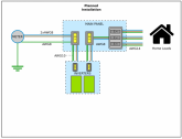
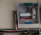
So im cabling my inverters:

1591029909092.png

And i just realized that the cables coming from the utility to my main panel are too thin!, house its old and the electrician decided that 2xAWG14 its enough for a full home.

I don't have heavy loads, so all this time i didn't have a single problem, however with the new inverters and my 12 x 380W panels i have almost 4000W of PV energy. The question is, in grid tie systems, are this inverters capable to backfeed to the grid the full 4000W of maximum PV power? (Considering no active loads at home, and 100% backfeeding).

1591030221210.png

If thats the case, im in problems and should change said cables:

- 2xAWG14 THW are capable of 20amps.
- If inverters can output 4000W to the grid (probably less from the losses), i should have at least 2xAWG10 for 40A!..


------------

Bonus questions!.

1.- Can anyone confirm if the inverters have anti-islanding protection?. I will test them but would be nice to know before hand!.
2.- Does anyone by any chance have the CE Certificate of LV2424 and the datasheet?. Supplier is slow to answer and i would need them to check with the utility company if i can interconnect with them.
 

Attachments

  • 1591030210188.png
    1591030210188.png
    160.8 KB · Views: 5
Last edited:
We are not sure of your country, electrical codes, or voltage.
The image from data sheet suggests each inverter is 120V because it mentions split-phase.
If you have only 120V, you are correct that 10 AWG minimum would be desired to deliver 4 kW.

Is the quad breaker on the right DC, and the black cables are DC from PV?
Breaker on the left appears to be AC. Is that the grid connection for the inverters? Each inverter ought to have its own breaker, no larger than the maximum according to data sheet, but 25% larger than maximum current inverter is supposed to deliver. But if it is a 15A breaker (because that's all that can go into the grid) then this isn't so bad. Just don't want a 40A breaker feeding two circuits each 14 AWG or 20 AWG, they would need separate 15A or 20A breakers.

"Hybrid" inverter - Some inverters act as a UPS, providing power to loads whether grid is up or not. You may be able to program them so no more than 15A is ever drawn from grid or delivered to grid, but your house can have 30A or 40A, "increased self consumption" by drawing from battery/PV when your house uses more than grid can supply. Would be good to add a relay to disconnect your extra load (e.g. washing machine?) if battery gets low, so so protected loads such as communication devices continue to operate. This all assumes the inverter has two AC connections - one for the grid and one for your loads.

I believe that is the case, so you want to wire Grid --> LV2424 --> protected loads:

https://www.mppsolar.com/v3/split-phase-lv-series/#

Only 14 awg feeding the entire house?? When you say "2xAWG14" do you mean one hot wire and one neutral, so a single 14 awg carries all the current?

The ampacity of 14 awg with 90C insulation is actually 20A, but our code limits us to 15A breaker or fuse for such circuits. That makes it safe even for repeated overloads that trip the breaker. (Each time a 22A load is applied, the breaker takes about 10 minutes before tripping, low enough to not bake the insulation. If a 20A breaker, the 30A it carries would damage insulation over time.)

How and where you tie these inverters into your system is important. If 14 awg is used for wiring throughout the house, you shouldn't tap the inverters into the same branch. They could deliver 15A which along with 15A coming from grid would be 30A your loads could draw without tripping a breaker. The wires can't carry that. The inverters need to land on the main panel with their own breaker.

Do you have a main breaker panel? (if so what current rating?) Or a fuse box?

Your battery should have a fuse. I think you have 3 strings of 2 PV panels into each inverter; more than 2 parallel strings should have fuses. You can get MC-4 fuse holders.
 
Actually, while 10 AWG would carry 40A, our code specifies 30A max breaker:


Ideally you would use 8 AWG, which with 90 degree insulation is good for 55A, and a 50A breaker.
This is enough above the continuous current from both inverters combined to avoid nuisance tripping. Each inverter would also have its own smaller breaker.

You calculated 2000W limited by panels, but inverters are rated 2400W. Panels do produce more than 100% sometimes (extra light bouncing off clouds) and wiring should be designed accordingly, unless you have programmed the inverter to limit at 2000W AC backfeed. Using 10 AWG and 25A or 30A breaker for each inverter might be appropriate (after combining those circuits, 8 AWG and 50A breaker is still good.)

I think I found a manual for monitoring software, which describes some inverter operating modes:


... and a data sheet showing 120/240V split phase and wiring as a UPS:


... but not the installation manual.
 
We are not sure of your country, electrical codes, or voltage.
The image from data sheet suggests each inverter is 120V because it mentions split-phase.
If you have only 120V, you are correct that 10 AWG minimum would be desired to deliver 4 kW.

Im in America, we use 120V and our code its derived from NEC, so its practically identical. I will switch my 2xAWG14 wires, to AWG10.
Is the quad breaker on the right DC, and the black cables are DC from PV?
Breaker on the left appears to be AC. Is that the grid connection for the inverters? Each inverter ought to have its own breaker, no larger than the maximum according to data sheet, but 25% larger than maximum current inverter is supposed to deliver. But if it is a 15A breaker (because that's all that can go into the grid) then this isn't so bad. Just don't want a 40A breaker feeding two circuits each 14 AWG or 20 AWG, they would need separate 15A or 20A breakers.

Correct, right panel its for DC, all the AWG8 black cables are from the 2 PV arrays, and correct again about the AC remarks.

Its great that you mention this as i was not totally sure about my cabling on the inverters, at first i tough about individual brakers, specially for servicing them.... howemever i ended up following the manufacturer diagrams:

1591108124078.png1591108257230.png

Basically the inverters are in parallel connected to a single breaker, i ended up choosing 60A for it. Maybe there could be problems if you switch off one of the inverters while they are connected in parallel, so thats why the manufacturer ask for this connection?.

In the photo you can see only the output breaker, im still missing some connections. From the main panel the house its divided in about 3 circuits, so im thinking that i could keep the inverters in the same line, and then use individual breakers for that output:

1591109357304.png


"Hybrid" inverter - Some inverters act as a UPS, providing power to loads whether grid is up or not. You may be able to program them so no more than 15A is ever drawn from grid or delivered to grid, but your house can have 30A or 40A, "increased self consumption" by drawing from battery/PV when your house uses more than grid can supply. Would be good to add a relay to disconnect your extra load (e.g. washing machine?) if battery gets low, so so protected loads such as communication devices continue to operate. This all assumes the inverter has two AC connections - one for the grid and one for your loads.

I believe that is the case, so you want to wire Grid --> LV2424 --> protected loads:

https://www.mppsolar.com/v3/split-phase-lv-series/#

Yeah i can configure low power draw from utility in the inverters for the battery chargers, but i dont think they have control about the current for when they are workin as bypass from utility to loads... so when im not running solar or batteries i can have more current passing than desired. But as i mention somewhere, the entire house has been working for many years with a single 20A fuse for everything!, so the main motivation to fixing the utility cables is to avoid problems while back feeding the 4000W to the grid. House has been working allright for many years with a single 20A fuse for everything, so we really dont have big current drawers in the installation.

The inverters indeed have separate input / outputs, and im planning on using them to run the whole house. In cause of extended power failures we will turn off all no essentials and leave the battery power just for the fridge and lights... and if battery became too low it can disconnect itself automatically. Also i have an small honda generator for this scenario.

Only 14 awg feeding the entire house?? When you say "2xAWG14" do you mean one hot wire and one neutral, so a single 14 awg carries all the current?

The ampacity of 14 awg with 90C insulation is actually 20A, but our code limits us to 15A breaker or fuse for such circuits. That makes it safe even for repeated overloads that trip the breaker. (Each time a 22A load is applied, the breaker takes about 10 minutes before tripping, low enough to not bake the insulation. If a 20A breaker, the 30A it carries would damage insulation over time.)

How and where you tie these inverters into your system is important. If 14 awg is used for wiring throughout the house, you shouldn't tap the inverters into the same branch. They could deliver 15A which along with 15A coming from grid would be 30A your loads could draw without tripping a breaker. The wires can't carry that. The inverters need to land on the main panel with their own breaker.

Yeah, right now its one hot, and one neutral AWG14 for the whole house. The utility meter its grounded, but they didnt event passed the ground cable to the main panel, all house contacts are groundless, a real mess.

This is my plan:

1591110594283.png

Your battery should have a fuse. I think you have 3 strings of 2 PV panels into each inverter; more than 2 parallel strings should have fuses. You can get MC-4 fuse holders.

Batteries have individual fuses (120A). The PV panels are connected to two fuses, 40A each (They work as fuse / switch in the panel). Not sure if i should also fuse them at the array itself.. as right now they are fused at the end of the line.

--

@Hedges, i really appreciate that you take your time to help me with my installation, im learnin a lot with our conversations, thanks!!
 
Actually, while 10 AWG would carry 40A, our code specifies 30A max breaker:


Ideally you would use 8 AWG, which with 90 degree insulation is good for 55A, and a 50A breaker.
This is enough above the continuous current from both inverters combined to avoid nuisance tripping. Each inverter would also have its own smaller breaker.


Hello again!.

I will take in consideration the sizing of the cable. Ill try to put 2xAWG8 with the 50A breaker. If they cannot fit in the conduit, im not sure what i can do, since the 30A breaker with AWG10 will maybe trip alot if we are feeding the grid with the full PV power. Maybe i will end up opening the wall to put a big conduit and fit all my giant cables. Also if i put 2xAWG8 for AC, i figure the ground should be changed to 6AWG?.
Actually, while 10 AWG would carry 40A, our code specifies 30A max breaker:


Ideally you would use 8 AWG, which with 90 degree insulation is good for 55A, and a 50A breaker.
This is enough above the continuous current from both inverters combined to avoid nuisance tripping. Each inverter would also have its own smaller breaker.

You calculated 2000W limited by panels, but inverters are rated 2400W. Panels do produce more than 100% sometimes (extra light bouncing off clouds) and wiring should be designed accordingly, unless you have programmed the inverter to limit at 2000W AC backfeed. Using 10 AWG and 25A or 30A breaker for each inverter might be appropriate (after combining those circuits, 8 AWG and 50A breaker is still good.)

I think I found a manual for monitoring software, which describes some inverter operating modes:


... and a data sheet showing 120/240V split phase and wiring as a UPS:


... but not the installation manual.

I dont think the inverter have an option to limit the AC backfeed, maybe @erik.calco can answer this?. The inverters are 2400W each, but the maximum PV power its 2000W according to specs. I have 2220 Watts of PV panels... can the MPPT's work with the extra power?. I some thread we were discussing that a lower overwattage might not affect them negatively... but not sure if they will just not be used (Wasted power), or they will effectively send that full power to the inverters.

Installation manual: http://www.mppsolar.com/manual/SPLIT PHASE LV/LV2424 hybrid manual-20190717.pdf
 
The vendor's recommendation of 80A to 360A AC fuse is almost certainly incorrect or incomplete. The wires to the inverter can't handle 80A. In case of a fault in the wiring or in the inverter, the wire would overheat. I think each individual inverter should have a breaker or fuse on its input, also on its output.

What I did for my Sunny Islands (seen in my picture) is I had two, 100A fuses coming from the main, split to four, 63A breakers (2 x 2 pole) feeding the 2s2p split & paralleled 120V inverters. On the output I landed them on 2 x 2 pole 70A breakers feeding another panel. My loads and grid-tie inverters are in that panel.

A problem I had, which you might also, is balance of current passing through paralleled inverters. Just running your house off batteries it is no problem because each inverter decides how much current to deliver. But pass-through from the grid, instead of balanced current I had about 75%/25% split instead of 50%/50%. Problem was the 70A QO model breakers, which had differing resistance. IF yours works as on-line UPS, converting all AC to DC and back to AC, it will self-limit. But if it has a relay connecting grid to loads like mine, resistance of wires is all that balances current between parallel paths. Mine came with instructions to match wire lengths but I found the breakers caused a problem.

How large is the feed-in from utility, and does it have a main fuse/breaker? If you can change the wires, I assume it does; how big is that breaker? If not, you can't isolate it; need utility company assistance (they yank the meter.) You would also have to consider how much current their wires can deliver.

Your planned installation shows 60A breaker. That should get 6 AWG wires.
I'm not aware of code requiring ground larger than supply wires (e.g. 6 AWG ground with 8 AWG supply). I see equal or smaller. The supply wires carry current continuously and get hot. The smaller ground only needs to carry a very high (about 5x) current for a few milliseconds until the fast magnetic trip happens or fuse blows. It never has time to get hot. This has a chart saying 10 AWG copper ground for a circuit with 60A breaker:


The PV panels will have a label for maximum fuse, probably 10, 15, or 20A. If only 1 or 2 strings probably no fuse is needed, or if included in disconnect the size doesn't matter. If 3 strings in parallel then use fuses. Could be MC-4 fuse holders where wires join or other types if in a box.

You say 40A fuse/switch at the panel. 40A should have 8 AWG (which is OK up to 50A or so). But wires to individual PV panels are probably 14, 12, or 10 AWG so need smaller fuses if there is a source that can supply more current. If your inverter accepts 3 panels series, 2 parallel, of without Voc being excessive even on a cold day, fuses can be eliminated. A 40A breaker for disconnect or just a switch no fuse is probably OK. But if 2s3p, then use separate fuse per string.

I see what you mean about PV vs. inverter power. The PV --> battery is limited to 2000W. The battery --> AC is 2400W. Since this inverter can backfeed the grid, it PROBABLY only does so when PV production exceeds battery charge, doesn't draw down the battery for backfeed. But I'm not sure. Some systems are meant to do that, and some are meant to just draw enough from battery to avoid using grid during some times of day. It's all software and sensors.

I think this inverter can limit grid current, both power draw and backfeed, by measuring current and supplying from battery. So you should be able to get 15A from the grid and feed 40A to the house, with the inverter supporting "additional local consumption". You just need to shut off your excessive loads when batteries get low. My Sunny Islands have programmable relays to signal "battery low, shed loads" and "battery full, feel free to run the electric water heater"

Skimming through your manual,

"Note1: Also, you can use 40A breaker for 2.4KW/3KW and 50A for 4KW/5KW for only 1 unit and install one breaker at its AC input in each inverter."

So one 40A breaker per inverter (input side), not a single 80A breaker with wires to both inverters. Even though their schematic shows one breaker for two or more inverters. They seem to recommend a single breaker, but it is too large for the wires, would not be safe or meet code.

You're going to have to read and understand that manual in detail! (and then know when not to do what they say, make sure every wire is sufficiently protected.)
 
The vendor's recommendation of 80A to 360A AC fuse is almost certainly incorrect or incomplete. The wires to the inverter can't handle 80A. In case of a fault in the wiring or in the inverter, the wire would overheat. I think each individual inverter should have a breaker or fuse on its input, also on its output.

I think the reason for this values is that they calculate total current demand in maximum AC charging & AC bypass scenario.
  • Not sure if when running from AC, the inverter its just a passtrough, or it converts to AC to DC and then AC again (Most likely first option). But in any case, there is 20A just from utility "Passtrough"
  • The unit can charge batteries up to 60A, wich at 29V its around 1800W. So thats around 15A AC
  • So total posible power consumption its 35 - 40A considering that its not 100% efficient.
I think thats why manufacturer recomends 40A for each inverter, and 80A for a parallel installation. This calls for really big cables!, and as you mention probably not good with US code.

What I did for my Sunny Islands (seen in my picture) is I had two, 100A fuses coming from the main, split to four, 63A breakers (2 x 2 pole) feeding the 2s2p split & paralleled 120V inverters. On the output I landed them on 2 x 2 pole 70A breakers feeding another panel. My loads and grid-tie inverters are in that panel.

A problem I had, which you might also, is balance of current passing through paralleled inverters. Just running your house off batteries it is no problem because each inverter decides how much current to deliver. But pass-through from the grid, instead of balanced current I had about 75%/25% split instead of 50%/50%. Problem was the 70A QO model breakers, which had differing resistance. IF yours works as on-line UPS, converting all AC to DC and back to AC, it will self-limit. But if it has a relay connecting grid to loads like mine, resistance of wires is all that balances current between parallel paths. Mine came with instructions to match wire lengths but I found the breakers caused a problem.

This can be one of the reasons of why the manufacturer recomends a parallel installation with a single breaker and the same cable line?. I've read about this in the Wiring Unlimited manual, page 54. Basically the inverters and breakers are not equall, they might have small diference in the internal resistance of the contactors, further compunded if your wiring has not perfectly matched lengths. This results in big relative differences, causing one inverter to carry much higher current than the other.

Most interesting its the cabling issue, this is one of the few applications where a cable too thick can be a problem!... as they will have very low impedance, wich can result in bigger relative differences between strings:

1591118823949.png

Im personally using 10AWG for the inverters, and the cables are perfectly matched to the milimiter level :).

How large is the feed-in from utility, and does it have a main fuse/breaker? If you can change the wires, I assume it does; how big is that breaker? If not, you can't isolate it; need utility company assistance (they yank the meter.) You would also have to consider how much current their wires can deliver.

The feed in from utility are very thick, 6 AWG most likely. Doesnt have a braker, i can yank the meter without problems and put cables from there to the house to my main breaker.

Your planned installation shows 60A breaker. That should get 6 AWG wires.
I'm not aware of code requiring ground larger than supply wires (e.g. 6 AWG ground with 8 AWG supply). I see equal or smaller. The supply wires carry current continuously and get hot. The smaller ground only needs to carry a very high (about 5x) current for a few milliseconds until the fast magnetic trip happens or fuse blows. It never has time to get hot. This has a chart saying 10 AWG copper ground for a circuit with 60A breaker:

I had that conception that can be erroneous, but somewhere ive read / hear that ground should be always bigger than your main conductors. Mainly because in case of fault you want the current to go easier to the cable with least impedance??.... Not sure, in any case i will go with that NEC table and use 8AWG supply wires with 8AWG grounding.

The PV panels will have a label for maximum fuse, probably 10, 15, or 20A. If only 1 or 2 strings probably no fuse is needed, or if included in disconnect the size doesn't matter. If 3 strings in parallel then use fuses. Could be MC-4 fuse holders where wires join or other types if in a box.

You say 40A fuse/switch at the panel. 40A should have 8 AWG (which is OK up to 50A or so). But wires to individual PV panels are probably 14, 12, or 10 AWG so need smaller fuses if there is a source that can supply more current. If your inverter accepts 3 panels series, 2 parallel, of without Voc being excessive even on a cold day, fuses can be eliminated. A 40A breaker for disconnect or just a switch no fuse is probably OK. But if 2s3p, then use separate fuse per string.

- They are rated for 15A fuse, the voltaje would be around 80V with 2200W, so thats 30A. The guy that installed the panels recomended a 40A fuse so it doesnt trip at maximum power, (maybe wrong advice?)...

- I have 2S3P, they have around 100V maximum VOC and normal voltaje around 80V. So if i understand this correctly, i should put a 30A fuse in each serial string (3 fuses for the total array), in the combiner box / MCY placed in the roof, and then leave my 40A fuse / switch at the panel?.

- The panels are attached together at the roof, and then conected to a single 2xAWG6 cable for array #1 (it has like a 30mt run), and 2xAWG10 for array #2 (around 10mt long).

I see what you mean about PV vs. inverter power. The PV --> battery is limited to 2000W. The battery --> AC is 2400W. Since this inverter can backfeed the grid, it PROBABLY only does so when PV production exceeds battery charge, doesn't draw down the battery for backfeed. But I'm not sure. Some systems are meant to do that, and some are meant to just draw enough from battery to avoid using grid during some times of day. It's all software and sensors.

I think this inverter can limit grid current, both power draw and backfeed, by measuring current and supplying from battery. So you should be able to get 15A from the grid and feed 40A to the house, with the inverter supporting "additional local consumption". You just need to shut off your excessive loads when batteries get low. My Sunny Islands have programmable relays to signal "battery low, shed loads" and "battery full, feel free to run the electric water heater"

- Yeah im almost 100% sure the inverter wont take any power from battery to backfeed to the grid, only excess PV power. But what happens if im not charging the batteries and the whole house its unoccupied?... maybe they will backfeed almost all PV power available.

The inverter can shutoff battery supply at programable lower voltage, and from there run over Utility if PV its not available, so not worried in this regard. You can program by software what your priority sources are, PV, Battery or Utility:

1591120215241.png
Reference: https://diysolarforum.com/threads/mpp-solar-lv2424-kicks-butt.5852/

So considering all of this, im coming to this almost-conclusions:

  • I will try to never recharge batteries from AC, all the time solar if possible. If the need calls for AC charging, it would be limited by 40amps, and ill try to avoid large loads while the rare event of AC charging. This removes the need for larger 80A fuse (40A per inverter). Im probably going for 50A for main fuse and AWG8 THW 90C conductors for Utility > Inverters.
  • Still not sure if i will place a separate breaker for each inverter as i don't want to get in to unbalance distribution of power between inverters. Most likely im doing it, but taking good care in the cabling to be equal, in that case i will use 25 to 30A fuses for each string.
  • AWG8 Conductors and ground form Utility to main panel. From there AWG10 for each individual string of inverters, and AWG14 for each substring of the house.
1591121595979.png

Really enjoying all this text walls :)
 

Attachments

  • 1591121488961.png
    1591121488961.png
    163.7 KB · Views: 4
Last edited:
No harm is making ground conductor larger than supplies, just not required.

"Im personally using 10AWG for the inverters, and the cables are perfectly matched to the milimiter level"

Longer is better in this case (and thinner as you say). i have 40' of 6 AWG from where the wires split near main panel to input. Another 20' of 6 AWG from output to where they join at another panel. So long as I don't use those 70A QO breakers which caused a problem, current is matched within resolution of display, e.g. 3.1 kW on one inverter and 3.2 kW on another (backfeeding grid from PV grid-tie inverters.)

"i should put a 30A fuse in each serial string (3 fuses for the total array), in the combiner box / MCY placed in the roof, and then leave my 40A fuse / switch at the panel? "

No, 15A fuse for each PV string; that protects the wire to the panels. Keep the 40A protection for the combined wire, ideally near the inverter, or up to 70A, for 6 AWG. The other string with 10 AWG ought to have 30A protection, but that may trip with 3 parallel strings. Although 10 AWG can carry 40A, our code calls for 30A protection.

"Still not sure if i will place a separate breaker for each inverter as i don't want to get in to unbalance distribution of power between inverters "

I had no problem with DIN-mount Schneider 63A supplemental breakers (which look like your photos.) They were well enough matched low resistance. It was just the QO plug-on breakers which were unmatched. It is possible they were counterfeit.

What are the complete specs for the PV panels? Especially Voc and temperature coefficient of voltage, typically quoted as either volts/degree or percent/degree? Evaluating that plus the record coldest temperature of your location may show that 3s2p remains under the 145V max spec of your inverter. In that case you can run higher voltage, lower current, fewer if any fuses, less power loss. Although, if over 115V (max MPPT of your inverter) it might not turn on. You live in a warm climate so maybe not a problem.
 
Looking at your planned system diagram, I see 50A breaker and 8 AWG from meter, which looks OK by the tables. But if it was me I'd probably put in 6 AWG if the utility drop is that large just for future loads. For instance, run an electric dryer or water heater from utility, not from inverters.

Looks like you have the house fed from the UPS inverters, which is nice, but if they fail it would be convenient to have a transfer switch. I do that with interlocked main and backfeed breakers in a Square-D QO panel. If you are using DIN mount breakers, you can get an interlocked quad (or maybe dual) breaker. I got one which has four, 63A breakers. That gives me split-phase 63A coming from utility and split-phase 63A from a generator. Only one can be connected at time. If you only have single phase at the meter you don't need as many poles. But since you have two inverters, the 4-pole could be used to combine them and make sure you don't transfer only one, not the other.

https://www.fronelec.com/products/mcb-double-power-interlock-circuit-breakerdz47-type

You show three 20A breakers feeding 14 AWG circuits. That exceeds our US NEC codes (which call for 15A breakers) although the wires can actually carry 25A. Hope you don't trip them often because after maybe 100 overloads the insulation will be dried out and cracking. We get to load larger wires more heavily; they go to a single appliance. But 14 or 12 AWG wiring to electric outlets are easy to overload with multiple appliances so the code is more conservative.

I'm not completely clear on your 10 AWG and 25A breakers. If one wire, one breaker that's fine. But one 10 AWG wire going to two 25A breakers for two inverters would exceed the 40A limit.

I've broken a few rules and melted a few wires, just not inside walls. I find it best to only break one rule at a time; it's when I break multiple rules that the conservative safety margins aren't enough.
 
No, 15A fuse for each PV string; that protects the wire to the panels. Keep the 40A protection for the combined wire, ideally near the inverter, or up to 70A, for 6 AWG. The other string with 10 AWG ought to have 30A protection, but that may trip with 3 parallel strings. Although 10 AWG can carry 40A, our code calls for 30A protection.

Perfectly clear now, i was adding up amps in a serial circuit!. 6 x 15A fuses for all my strings. Generall 40A fuse for 6AWg array. Will try to source a 32 - 36 fuse if possible for AWG10 string, also i think i need better protection in that one, since the cables are snug together very ctight in the conduit, so i should probably down rated them a bit.

I had no problem with DIN-mount Schneider 63A supplemental breakers (which look like your photos.) They were well enough matched low resistance. It was just the QO plug-on breakers which were unmatched. It is possible they were counterfeit.

You convinced me :), ill put individuall breakers for the inverters!.

What are the complete specs for the PV panels? Especially Voc and temperature coefficient of voltage, typically quoted as either volts/degree or percent/degree? Evaluating that plus the record coldest temperature of your location may show that 3s2p remains under the 145V max spec of your inverter. In that case you can run higher voltage, lower current, fewer if any fuses, less power loss. Although, if over 115V (max MPPT of your inverter) it might not turn on. You live in a warm climate so maybe not a problem.
  • Lowest temperature register in the city was -1C, but thats extremely rare.
  • VOC its 48V, Max Power 370W, Maximum power voltage 39.4V
  • Indeed a warm place, average in summer around 35C, and winter around 25C
1591126353904.png

Code:
Inverter maximum input voltage with the temperature coefficient percentage of the VOC calculation:
(STC temp – low temp) x temp coefficient % VOC x VOC + VOC = VMax
Inverter max voltage / VMax = Maximum modules per series string

27 x 0.0030 = 0.078
0.081 x 48V = 3.74V
3.11 V + 48V = 51.11 VMax

VOC LIMITS
Inverter MAX = 145V
2 x Series = 102.22V
3 x Series = 153.33V

Operating Voltage LIMITS
Inverter MPPT = 30 - 115Vdc
2 x Series = 78.8V
3 x Series = 118.2V

So i think a 3xSeries might not be adviseable as i can exceed the ratings in both scenarios.. what do you think?

  • Im not overly worried about VOC, since that record low its recorded during night, at sunset / dawn its around 5C average.
  • But the power voltage can be a problem, in some of this forum discussions ive read about the probability of the inverter failing by just a little overvoltage, but not sure about this in reality.
Need to double check about all of this, since 3 x Series as you mention would be very beneficial, but the inverters probably cant handle it.


Looks like you have the house fed from the UPS inverters, which is nice, but if they fail it would be convenient to have a transfer switch. I do that with interlocked main and backfeed breakers in a Square-D QO panel. If you are using DIN mount breakers, you can get an interlocked quad (or maybe dual) breaker. I got one which has four, 63A breakers. That gives me split-phase 63A coming from utility and split-phase 63A from a generator. Only one can be connected at time. If you only have single phase at the meter you don't need as many poles. But since you have two inverters, the 4-pole could be used to combine them and make sure you don't transfer only one, not the other.

https://www.fronelec.com/products/mcb-double-power-interlock-circuit-breakerdz47-type

Jeje im planning a "Manual transfer switch" with a single breaker, simplified here:

1591127485100.png

So when i want to bypass the inverters, i turn off the both inverter breakers, and turn on the transfer switch.
I will search for your interlock breaker as would be a much safer solution. Im not sure about what could happen if i turn on the transfer switch while the inverters are working, but my instinct says nothing good. In a regular inverter maybe the sinowaves are not matched and that could ruin things...


You show three 20A breakers feeding 14 AWG circuits. That exceeds our US NEC codes (which call for 15A breakers) although the wires can actually carry 25A. Hope you don't trip them often because after maybe 100 overloads the insulation will be dried out and cracking. We get to load larger wires more heavily; they go to a single appliance. But 14 or 12 AWG wiring to electric outlets are easy to overload with multiple appliances so the code is more conservative.

I'm not completely clear on your 10 AWG and 25A breakers. If one wire, one breaker that's fine. But one 10 AWG wire going to two 25A breakers for two inverters would exceed the 40A limit.

I've broken a few rules and melted a few wires, just not inside walls. I find it best to only break one rule at a time; it's when I break multiple rules that the conservative safety margins aren't enough.

Thanks!, i was considering the existing breakers... i will place 15A breakers in that case.

About the 25Amps breakers, its a single wire:

1591129330420.png

Diagram getting bigger!


I've broken a few rules and melted a few wires, just not inside walls. I find it best to only break one rule at a time; it's when I break multiple rules that the conservative safety margins aren't enough.

Agree!, and thanks to your help im not burning my house!. Im being kind of conservative as my loads are very low, around 12Kwh /day and not AC's or big consumers, i think my biggest appliances are the microwave / air compresor, both sub 1.5Kwh... so i was probably good with a single inverter. But i prefered to oversize to be safe. The house side would never see >20A on the AC lines.. as my actual breaker has never jumped.... but the Utility side might see some high amps if inverters backfeed all the PV power. That was the whole reason of the post, but im very happy that i have a much safer / better calculated system now.
 
If four current-carrying conductors (from PV) are in a conduit, the NEC ampacity table says to derate to 80%. Your 10 AWG if rated 90 degree C has 40A ampacity (and 30A max breaker.) Derated to 80% it has 32A ampacity, still allowed 30A breaker. With PV Imp = 9.40A x 3 strings, you would like 35A breaker (25% above) to avoid nuisance tripping.

If you orient some strings at winter AM sun, some at winter PM sun, some at summer Noon sun, the peak current would be lower so maybe never over 24A and a 30A breaker would be fine. Would have been easier to use 8 AWG for all panels, rather than 6 AWG for some and 10 AWG for the others (just wastes a bit more IR drop.)

Your equations show 0.003 which is around typical temperature coefficient, although I don't see it on the label.
You're right with 48Voc on the label, 3 in series is too much. So 2s3p with fuses is good.

Having the large fuse on DC at the inverter in addition to the ones for individual strings is good because an inverter failure could dump battery current through that wire (in case of multiple faults.) Looks like you will have that.

Single breaker transfer switch is risky. May blow up inverter if grid is live, may electrocute lineman if grid is down and you don't disconnect the other breaker. There are SPDT and DPDT knife type transfer switches. There are relays, but I've had them weld and make a diagonal connection. There are the interlocked breakers which seem the most expedient. My installation began with a visible blade DPST knife switch, required by the utility so they could be confident it was disconnected if they decided to do so manually. Later, they offered the option of no switch but they might unplug our meter. In all cases they were aware we had grid-tie PV and gave permission to connect.

Separate 10 AWG before and after the 25A breaker looks good.
You still have a "T" tapping neutral. That would now carry 25A to inverter + 50A to secondary panel. Should have separate wires for each back to main breaker. Probably just not a 100% accurate drawing yet.

12 kWh/day? I estimate 19 kWh/day average from your panels so you can get away with more consumption like a window A/C if you like. Shorter days may come in closer to 12 kWh but won't be as hot.

Air compressor - some big induction motors are hard to kick over. They other guys may have experience with your brand of inverter. 1.5 kW @ 120V is probably 1.0 or 1.5 HP if induction motor but may draw 50A starting. Other type motors aren't so bad. Your two inverters total 5 kW so just might do it!
 
I saw your battery is 560 Ah. 12 kWh at 24V is 500 Ah. Considering depth of discharge and cycle life, so long as your consumption is spread over the day that should be great. During dark times you still have the grid to charge, and batteries let you have occasional higher consumption. If grid is down, PV and battery should carry you through so long as you don't also have multiple stormy days.

My system has AGM lead-acid, 20 kWh @ 48V but about 14 kWh usable at 70% DOD. My PV is way oversized compared to that. I can barely make it through the night on batteries, have to manually disconnect some things. Looks like my furnace frequently cycling the fan due to a control fault is part of the problem, but otherwise mostly multiple refrigerators, yard lights, entertainment equipment.
 
Last edited:
If four current-carrying conductors (from PV) are in a conduit, the NEC ampacity table says to derate to 80%. Your 10 AWG if rated 90 degree C has 40A ampacity (and 30A max breaker.) Derated to 80% it has 32A ampacity, still allowed 30A breaker. With PV Imp = 9.40A x 3 strings, you would like 35A breaker (25% above) to avoid nuisance tripping.

If you orient some strings at winter AM sun, some at winter PM sun, some at summer Noon sun, the peak current would be lower so maybe never over 24A and a 30A breaker would be fine. Would have been easier to use 8 AWG for all panels, rather than 6 AWG for some and 10 AWG for the others (just wastes a bit more IR drop.)

Got it!. Unfortunately array #1 was installed with all the conduits and AWG6, so we were limited to 10AWG for the new array.

Your equations show 0.003 which is around typical temperature coefficient, although I don't see it on the label.
You're right with 48Voc on the label, 3 in series is too much. So 2s3p with fuses is good.

Having the large fuse on DC at the inverter in addition to the ones for individual strings is good because an inverter failure could dump battery current through that wire (in case of multiple faults.) Looks like you will have that.

Sounds great, i never see fuses at panel level, thats why i dont trust that much my local installers.

Single breaker transfer switch is risky. May blow up inverter if grid is live, may electrocute lineman if grid is down and you don't disconnect the other breaker. There are SPDT and DPDT knife type transfer switches. There are relays, but I've had them weld and make a diagonal connection. There are the interlocked breakers which seem the most expedient. My installation began with a visible blade DPST knife switch, required by the utility so they could be confident it was disconnected if they decided to do so manually. Later, they offered the option of no switch but they might unplug our meter. In all cases they were aware we had grid-tie PV and gave permission to connect.

Understood, i will update and remove the single breaker.

Separate 10 AWG before and after the 25A breaker looks good.
You still have a "T" tapping neutral. That would now carry 25A to inverter + 50A to secondary panel. Should have separate wires for each back to main breaker. Probably just not a 100% accurate drawing yet.

Now i have some doubts, updatind drawings:

1591134130412.png

  • I was planning on using a single AWG10 wire for but input and output of the inverter neutrals / grounds. All the neutrals arribe to the busbar in the panel, wich is represented with the dotted line. Main braker and secundary panels are the same panel, but for abstraction purposes i draw it like that:
1591134434615.png
Not sure if i should put separated cables for neutral IN / OUT, my logic says its OK with a single one. And 99% sure its the same case for grounding :).

12 kWh/day? I estimate 19 kWh/day average from your panels so you can get away with more consumption like a window A/C if you like. Shorter days may come in closer to 12 kWh but won't be as hot. Air compressor - some big induction motors are hard to kick over. They other guys may have experience with your brand of inverter. 1.5 kW @ 120V is probably 1.0 or 1.5 HP if induction motor but may draw 50A starting. Other type motors aren't so bad. Your two inverters total 5 kW so just might do it!

I have a couple of panels with AP Microinverters, they are giving around 4Kwh / day, so 12 panels maybe up to 24Kwh!?... we have pretty good sun around here :).

Hopefully im ok around motors and such, if i start getting problems im planning on making an special receptacle bypassing the inverters for big current devices.

I saw your battery is 560 Ah. 12 kWh at 24V is 500 Ah. Considering depth of discharge and cycle life, so long as your consumption is spread over the day that should be great. During dark times you still have the grid to charge, and batteries let you have occasional higher consumption. If grid is down, PV and battery should carry you through so long as you don't also have multiple stormy days.

My system has AGM lead-acid, 20 kWh @ 48V but about 14 kWh usable at 70% DOD. My PV is way oversized compared to that. I can barely make it through the night on batteries, have to manually disconnect some things. Looks like my furnace frequently cycling the fan due to a control fault is part of the problem, but otherwise mostly multiple refrigerators, yard lights, entertainment equipment.

Yes hopefully can stay 90% of the year with just solar + PV!.... the nice thing about the inverters is that you can configure a different discharge voltage limit for when grid is available, so maybe i can discharge them to about 10 - 20% in normal days to extend lifecycles, and to almost empty during power shortages.

Whats your PV capacity?... thats a big battery bank. Plan on updating to lithium?, manually disconecting devices sounds like such a chore. We are fortunate to have a good climate while also having good sun for like 90% of the year :).. so the AC and heating are not completely necesary. Currently we are doing good with some evaporative coolers and a bunch of sweaters :), Its interesting that some of us around here consider good days the rainy ones, as we have the burning sun for all the year!
 

Attachments

  • 1591134399599.png
    1591134399599.png
    227.9 KB · Views: 2
"I was planning on using a single AWG10 wire for but input and output of the inverter neutrals / grounds. "

If an interlock ensures your have either 25+25 from inverters or 50 from main, then neutral currents wouldn't exceed 50A. So 8 AWG should be OK, but 10 AWG would be too small.

Just make sure return current has no choices, can only go through one properly sized neutral. If two in parallel it can put too much current through one.

Your photo shows two white wires going to two inverters, and one more white wire the same size probably going the rest of the house or grid. Sum of both inverter currents go through that one wire, too much. (because it is parallel; if they were split phase it would be the difference and no problem.) I think it needs to be 8 gauge. Same if you run one hot to the box and feed two 25A breakers. Then 10 gauge for hot and neutral to each breaker.


I happened to route neutral from main to other panel with 2 AWG (100A), and from other panel back to my inverters with 6 AWG (70A). I have hot in, hot out, single neutral, single ground to each inverter.

"I have a couple of panels with AP Microinverters, they are giving around 4Kwh / day "

Not sure how those will interact with LV2424. If on the grid side, grid-tie inverters just shut off when the grid goes down. If on the output of LV2424 they could force the voltage high on it. Maybe they shut off, maybe something goes wrong.

I've got something like 17 or 20 kW of panels installed now, with a couple different orientations. (not aimed at noontime sun so they produce less than ratings due to longer path through atmosphere.) When first installed, peak rates were Noon to 6:00 PM. Now, 4:00 to 9:00 PM which changes my desired orientation.

I just got these AGM, shorter cycle life but only expected to cycle during rare grid failures. Didn't want to pay the higher price for lithium with more cycles than I'll ever use. Batteries are only to keep the island grid alive during grid failures so I can use the PV during the day, and barely make it through the night. Peak charge rate would be about 0.7C but not likely to happen because by the time sun is so oriented the batteries would already have recharged.

Since my battery bank is too small, manual transfer lets me switch off yard lights, entertainment center. Otherwise, my power shuts off at 3:00 AM. More efficient refrigerator would reduce the load. Eventually I may set up controlled relays enabling laundry, etc. only if either on-grid or fully charged battery. I need to pull more wires before it is UPS, for now its like a backup generator.


I might get a small lithium bank for a pickup truck mounted system.
 
"I was planning on using a single AWG10 wire for but input and output of the inverter neutrals / grounds. "

If an interlock ensures your have either 25+25 from inverters or 50 from main, then neutral currents wouldn't exceed 50A. So 8 AWG should be OK, but 10 AWG would be too small.

Just make sure return current has no choices, can only go through one properly sized neutral. If two in parallel it can put too much current through one.

Your photo shows two white wires going to two inverters, and one more white wire the same size probably going the rest of the house or grid. Sum of both inverter currents go through that one wire, too much. (because it is parallel; if they were split phase it would be the difference and no problem.) I think it needs to be 8 gauge. Same if you run one hot to the box and feed two 25A breakers. Then 10 gauge for hot and neutral to each breaker.


I happened to route neutral from main to other panel with 2 AWG (100A), and from other panel back to my inverters with 6 AWG (70A). I have hot in, hot out, single neutral, single ground to each inverter.

Man you must think i love making diagrams.. i swear this is the last one!: :)

1591139444948.png
I wanted to make a panel level representation just to double check. As you can see im sharing the neutrals and grounds for both input / output for the inverters. In my mind thats ok as the neutral will either work as a return path for the maximum 2400W power of the inverter.
  • Solid lines are AWG8, dotted ones are AWG10.
  • Didnt show neutrals and grounds going to the house, but they are considered.. the drawing its a mess as it .
I happened to route neutral from main to other panel with 2 AWG (100A), and from other panel back to my inverters with 6 AWG (70A). I have hot in, hot out, single neutral, single ground to each inverter.

Well i could avoided all that drawing if i read this more carefully :) . Seems like you have the same setup only with monster cables. Well at least we have a new diagram and it has colors!

What are your wire gauges for inverter individual conections?

Not sure how those will interact with LV2424. If on the grid side, grid-tie inverters just shut off when the grid goes down. If on the output of LV2424 they could force the voltage high on it. Maybe they shut off, maybe something goes wrong.

The microinverters are in a separate electrical installation in the same "building", so they shouldnt be a problem. It would be interesting to know what will happen if they were to be conected to the output side of the inverters during shortages... my guess is that they will keep working and inject power to the house grid... but not sure if the inverters would like this.

Actually im planning on making a new post with a question regarding this. I have the 2 microinverted panels placed in Array #1 (Where i have 6 panels to grid tie inverters). However, they are sharing the same aluminum structure, and i dont know what the hell should i do with the grounding in this scenario. The building has 2 meters and 2 separate electrical installations. My country's code says i should delete ground from one of the meters and use one ground for all the building, but not sure about this.... well this is another subject as i mention!
I've got something like 17 or 20 kW of panels installed now, with a couple different orientations. (not aimed at noontime sun so they produce less than ratings due to longer path through atmosphere.) When first installed, peak rates were Noon to 6:00 PM. Now, 4:00 to 9:00 PM which changes my desired orientation.
Very interesting setup

I just got these AGM, shorter cycle life but only expected to cycle during rare grid failures. Didn't want to pay the higher price for lithium with more cycles than I'll ever use. Batteries are only to keep the island grid alive during grid failures so I can use the PV during the day, and barely make it through the night. Peak charge rate would be about 0.7C but not likely to happen because by the time sun is so oriented the batteries would already have recharged.

Thats smarter. Batteries are too expensive and if grid available its always cheaper (and probably more reasonable) to have small bank and maybe a genset for shortages. Howemever constant energy its very important for me, i have some small servers running that i dont want to mess with... so hopefully the system has enough power to feed them during cuts.

Whats the calendar lifespan for AGM's?, the price different isnt that big and with lithium maybe lasting +10yr it might be worth it in the long run. But also, in 5 - 8 yr we might have some interesting breaktroughs in battery technologies and lifepo4s could be rendered obsolet.
 
Hi,

Well, diagrams or photos are the best way for me to understand what you're doing and comment on it!

Same neutral to input and output of an inverter should be fine. My vendor expected those to pass through, but I only connected to one neutral terminal (and one ground). They are the same node internally, and no current measuring device or anything like that.

I suggest planning to be able to rip out the inverters for repair while leaving the house working, so separate neutral and ground from main panel to sub panel supports that. Breakers on input and output of inverters lets you turn off the wires before unscrewing them. The only thing you can't do right now is isolate one inverter while leaving the other connected. You'll have to shut off the remaining inverter momentarily while you remove its output wire from the 50A breaker on secondary panel. Color-code the wires so you know which is which.

Having two circuits (these inverters and micro-inverters) coming from different meters but both grounded to the same frame seems funny at first, but maybe not. If I have any two grounded pieces of equipment, that could happen. Imagine fans or pumps on multiple residential or commercial units - they have their own ground wire and they have a path through pipes or building structure.

My AGM batteries should have 10 year shelf or float life, 3 year cycle life to 50% DOD daily, 10 year to 20% DOD. The Lithium brands I saw for Sunny Island looked like they could have 30 year shelf life and 10 year 80% DOD daily. Cost of cycle life for any of them is greater than the spread between $0.45/kWh peak and $0.15 kWh off-peak. Flooded lead acid could be a bit cheaper, and people on this forum are building DIY lithium for cheaper.

I have service entrance of 2/0 for 200A main breaker. After that I either go through 200A main on my panel for everything and 70A for PV (270A total allowed with 225A rated busbar), or change out to 150A main so I can have 100A for PV, or leave the 200A main but tape before it with 100A fused disconnect. Regardless of all those, there is still that first 200A breaker at the meter, so I'll never exceed service entrance limit.

The 100A fused disconnect is used regardless, either as a line-side tap or off a 70A or 100A breaker, with 2 AWG. I put two dual 63A breakers inside the disconnect, so I get two red hots and two black hots, each of which has 6 AWG going to four Sunny Island. They can be programmed for 52A max each. I programmed the set for 90A total so it shouldn't ever blow the fuse.

Also four 6 AWG from four Sunny Islands to a 3rd panel (PV combiner) for hots. That is where I had those 70A QO breakers which caused an imbalance.

The 2" conduit was getting tight so I routed just two 6 AWG neutral from my 3rd panel back to the two split-phase pairs of inverters; it only carries the difference, not the sum. I also have 2 AWG neutral from the 200A panel to the 3rd panel. Used to just have red/black/white 2 AWG plus smaller ground from a breaker in the 200A panel to the 3rd panel. The red and green now go to an interlocked backfeed on the main panel; The wiring goes in circles, but if grid is down I can flip breakers and feed everything from my inverters. Later, I'll move some protected loads to the 3rd panel for UPS operation.

Because my PV is AC coupled not DC, there is a load-shed relay to disconnect just the loads while waiting for the sun to come back up. Separate DC charge controllers wouldn't need that, and your hybrid don't either. But, a low-battery disconnect of non-critical loads would help keep your servers up.

All this rigid conduit and copper cost a lot! 15 years ago I paid $4/watt for PV and $0.80/watt for grid-tie inverters. Recently I've paid $0.35 for PV and $0.12 for inverters. AGM batteries cost $0.25/Wh, and battery inverters cost $0.25/W
 
Same neutral to input and output of an inverter should be fine. My vendor expected those to pass through, but I only connected to one neutral terminal (and one ground). They are the same node internally, and no current measuring device or anything like that.

Oh great!, interesting to know that the IN / OUT are the same connector, ill check with mine but its probably the same, i was doing this wich might be unnecessary if that's the case:

1591159059815.png
I suggest planning to be able to rip out the inverters for repair while leaving the house working, so separate neutral and ground from main panel to sub panel supports that. Breakers on input and output of inverters lets you turn off the wires before unscrewing them. The only thing you can't do right now is isolate one inverter while leaving the other connected. You'll have to shut off the remaining inverter momentarily while you remove its output wire from the 50A breaker on secondary panel. Color-code the wires so you know which is which.

Time for new diagram!

1591161344321.png

  • I added a little more detail, first switch its the interlock breaker. with this configuration i can remove the inverters without shutting of the house i believe.
  • It might be valuable to independently manipulate the energy at inverter level, so ill add an additional pair of 25A breakers for the inverter outputs. (Not showed in the diagram)

Having two circuits (these inverters and micro-inverters) coming from different meters but both grounded to the same frame seems funny at first, but maybe not. If I have any two grounded pieces of equipment, that could happen. Imagine fans or pumps on multiple residential or commercial units - they have their own ground wire and they have a path through pipes or building structure.

Interesting... at the end all grounds are tied together!,think i might leave the 2 grounds and just tie them together at some point. In your opinion would be better to leave a simple ground for the whole building?, or separate interconnected grounds, one for each meter?.

My AGM batteries should have 10 year shelf or float life, 3 year cycle life to 50% DOD daily, 10 year to 20% DOD. The Lithium brands I saw for Sunny Island looked like they could have 30 year shelf life and 10 year 80% DOD daily. Cost of cycle life for any of them is greater than the spread between $0.45/kWh peak and $0.15 kWh off-peak. Flooded lead acid could be a bit cheaper, and people on this forum are building DIY lithium for cheaper.

Thats right, branded lithium batteries are still too expensive, in my project first iteration i went with lead acid as lithium were out of the question, those batteries cost more than my car... but some time later discovered the DIY battery world and ended up getting a new hobby.

My 6 x 370AH trojan were around 1200USD, with only 185Ah usable.
The 280Ah bank around 1500USD, all of them usable.

So it was an easy decision!

The 2" conduit was getting tight so I routed just two 6 AWG neutral from my 3rd panel back to the two split-phase pairs of inverters; it only carries the difference, not the sum. I also have 2 AWG neutral from the 200A panel to the 3rd panel. Used to just have red/black/white 2 AWG plus smaller ground from a breaker in the 200A panel to the 3rd panel. The red and green now go to an interlocked backfeed on the main panel; The wiring goes in circles, but if grid is down I can flip breakers and feed everything from my inverters. Later, I'll move some protected loads to the 3rd panel for UPS operation.

Man that's impressive, sounds almost like an industrial installation. Some people save their money under the mattress, some others inside 2" conduits

All this rigid conduit and copper cost a lot! 15 years ago I paid $4/watt for PV and $0.80/watt for grid-tie inverters. Recently I've paid $0.35 for PV and $0.12 for inverters. AGM batteries cost $0.25/Wh, and battery inverters cost $0.25/W

I can imagine!..... i had the itch for solar from around 10 years ago, but never did the final jump as i consider that the cost per watt was not good enough for my taste. With 370W panels at 150USD and the DIY batteries it was just the right moment to start!. Hopefully the wallet can handle the cost of the 8AWG and bunch of breakers that im buying next!
 
Last edited:
"I added a little more detail, first switch its the interlock breaker. with this configuration i can remove the inverters without shutting of the house i believe.
  • It might be valuable to independently manipulate the energy at inverter level, so ill add an additional pair of 25A breakers for the inverter outputs. (Not showed in the diagram)"
Better put that interlocked breaker on the output of the inverters, not the input!
As you have it now, you'll disconnect grid from input of inverter (making inverter think there is a power failure), and feed grid to the house loads, paralleled with the inverter output!

No need to interlock input to the inverter. That can be on or off.
You want the interlock to select either grid or combined inverters to feed the house, so grid and inverter output are never connected together.

Ideally you would get one 50A and two 25A interlocked, but I'm not sure if you can mix & match. If a 50A is acceptable on the output of the inverter (check the specs), then you can probably get an interlocked 2 pole + 2 pole 50A. Whatever the standard values are; I got that in 63A.
 
Morning!. I was planning in turning off the inverters first, then do the switching..., but you are right!, that setup its more easier / safer!

1591194084273.png

Btw im finding difficult to source the interlock switchs, most of them are from aliexpress so i dont think they are that reliable, altough i think we dont need them to be highly fail safe as we have the input protections from 25A breakers, and also output protection by the final 15A breakers.

Alternately, im looking at some din rail selectors switch's:

1591196709885.png

Might work!
 
Drawing looks good, properly locks out supplies to prevent fights! :)

Here's what I got but haven't used:


Here is something fancier:


Both are 63A.

What I used, because it fit my breaker panel:


(my cost from Home Depo about $60)


By the way, our codes don't allow two wires under one screw terminal. I don't think it is actually a problem with stranded wire, just solid wire, but codes is codes. Instead, I use:
1) wire nuts to join them to a third wire, which goes to the breaker
2) Set-screw or split-bolt connectors
3) For lugs, pull wire through and connect to a stripped center section (that gave me two ends for two DIN breakers connected to one fuse holder)

Make sure wire gauge can carry what you're doing. I had 2 AWG into 100A fuse, then 6 AWG into two 63A breakers. Couldn't daisy chain the breakers because that would be all 126A (or 100A limit due to fuse) through first length of 6 AWG. That's why two lengths of 6 AWG came from the 100A fuse, and each was limited to 63A.
 
Back
Top