rodrick
Free energy enthusiast
Yes you can’t have 2 mppts on a single array they will fight each other split the array up or use just one inverters mppt input


Would this cause the inverter damage? Like what I'm describing, a pop in the inverter?Yes you can’t have 2 mppts on a single array they will fight each other split the array up or use just one inverters mppt input
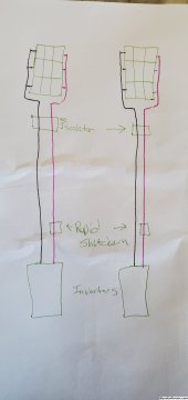
yesOk, so this is wrong? I just want to be clear.
This is the correct wayWould this cause the inverter damage? Like what I'm describing, a pop in the inverter?
Well this sucks, I changed to this because it's what tech support told me to do. Now I've got to pull the wires and run a second line. I've added a rought diagram, is this the way it should be? This is almost exactly my original plan. I do plan to add breakers for lightning, I read I needed them just recently in the manual.
Would this cause the inverter damage? Like what I'm describing, a pop in the inverter?
Well this sucks, I changed to this because it's what tech support told me to do. Now I've got to pull the wires and run a second line. I've added a rought diagram, is this the way it should be? This is almost exactly my original plan. I do plan to add breakers for lightning, I read I needed them just recently in the manual.
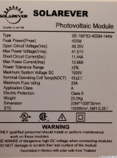
I have 3 panels in a series, 3 series per array, two arrays, total 18 panels. I think I have the 2023 upgraded inverters. I'll post their data plates so I get it right.What are your panel specs and how many panels in each array?
Your last picture is indicating like you will have 3p1s, is that true?
Or do you have 3 panels in series?
(EDIT: Actually yeah you do, I was blind, I see the separator lines in the picture now, looks like you have 3s3p)
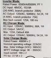
Is your inverter max PV input 250v (like the LV6548s)?
EDIT: What is your short-circuit amperage on each string? (panel Isc x 3)
I have 3 panels in a series, 3 series per array, two arrays, total 18 panels. I think I have the 2023 upgraded inverters. I'll post their data plates so I get it right.
Also to add, I order a 15a breaker for each array. My math puts them at 9.5a, that would make a 10a too small right?
Thank you. I did have an electrician help with the plans, but they didn't specialist in solar.With your 18 panels, you'd be way better off to string 6 panels series into single strings, and use 3 of the PV inputs on your 6548's... That would put your Voc at 296.1v (not correcting for temp coefficient of Voc, but well below PV max volts of 390v)..
Then Isc amps on each string would be at 11.44a (well below clipping point of 18a)... You'll get most power harvest this way.
Thank you. I did have an electrician help with the plans, but they didn't specialist in solar.
Sorry, I'm having a little trouble imaging that (could you scribble out a diagram?). I should put 6 panels in a series, and run three lines to the inverters (1pv1,1pv2, 2pv1)? My panels are set up and two separate frames about 10' apart with 9 panels on each. I also have 5 extra panels, my design changed a few times on the recommendation of "pros".
so your leaving production on the table if you do 3p into each MPPT
It's possible. Voltage is the one sure hard limit. Current is a little fuzzier, some MPPT will survive over current in the PV long term without issue. Others might notI'd actually go so far as to say that 3p could actually let the smoke out of the inverters since his inverter spec sheet said max PV Isc 22.5a, so in my eyes, 2p would max to even consider.
It's possible. Voltage is the one sure hard limit. Current is a little fuzzier, some MPPT will survive over current in the PV long term without issue. Others might not
Thanks to everyone who responded, I'm grateful. I've read over the posts, then with the advice given came up with some options that I have all the equipment to do right now.
I've always planned on an array 3, but due to permit limits I would need to hire an engineer for the third array if it was on the permit. That's why I have extra. Just sitting on top of the conex that stores my system, but over 6' high I have to pay an engineer to look over blueprints.
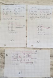
I've come up with about three configurations, I'm thinking of going with #1. But wanna see if you guys think the others are better. Thanks again for all your help.
Also to add, 1p1/1p2/2p1/2p2 are the panel input ports on the inverters.
I thought the SCC "amp limit discussion" ended with the amp limit being the extent of the reverse polarity protection. And, the SCC would only pull the amps it was capable of using.With the amp limit on your inverter you don't want any parallel strings.
I thought the SCC "amp limit discussion" ended with the amp limit being the extent of the reverse polarity protection. And, the SCC would only pull the amps it was capable of using.
Am i wrong? Still looking for that thread...
Thanks to everyone who responded, I'm grateful. I've read over the posts, then with the advice given came up with some options that I have all the equipment to do right now.
I've always planned on an array 3, but due to permit limits I would need to hire an engineer for the third array if it was on the permit. That's why I have extra. Just sitting on top of the conex that stores my system, but over 6' high I have to pay an engineer to look over blueprints.
I've come up with about three configurations, I'm thinking of going with #1. But wanna see if you guys think the others are better. Thanks again for all your help.
Also to add, 1p1/1p2/2p1/2p2 are the panel input ports on the inverters. Also realized I messed up #2's diagram. I put 2 strings in Parallel instead of 6 in a series.
After checking, I'll need to run another conduit if I do this because I can't run 8 cables in the current pipe I have. It's about 50' to the electronics, and I'll have to install another rapid shutdown. So #3 got far more complicated than I would have liked.The main reason I suggested your Option #3, is because I don't know how far apart your arrays are, the angles on them, where the conduits are, so my suggestion to go that way, was based on convenience, since you wouldn't have to string 3 panels and 3 panels on the same series string, attempting to span the wiring across the two physical arrays.
After checking, I'll need to run another conduit if I do this because I can't run 8 cables in the current pipe I have. It's about 50' to the electronics, and I'll have to install another rapid shutdown. So #3 got far more complicated than I would have liked.
#2 was your first suggestion. 6 panels in a string, 3 strings, each going to its own input. It would also be the easiest to wire as I wouldn't have to change much. There wouldn't be any issues other then just running them between the arrays, would there?