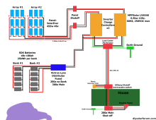
The way it is currently wired, you could feed AC power from 2 sources that are not in phase. This is dangerous if an interlock is not present.
The preferred method would be 200A service disconnect with N-G bond, then a 3 pole transfer switch which feeds a breaker panel. This allows switching sources from grid to alternatives into the breaker panel while breaking the N so there are not 2 points with N-G bond. The problem is 200A 3 pole transfer switches are not cheap. Adding another transfer switch ahead of the inverters would allow switching between generator and grid power into the inverter AC input. That could be 2 pole and the current switch you have would work.
Are you backfeeding a breaker in the 200A panel and is a interlock present? As for making the generator floating neutral, not required if you were to feed it into the inverter AC input or into a 3 pole transfer switch after the 200A service disconnect (the service disconnect contains N-G bond). This is how my system is wired, the inverters were later changed to LV6548's.
View attachment 175896
This allows the breaker panel on the right to be powered by grid or the inverters. I can completely bypass the inverters if needed. The problem with your system is you have 3 sources that are N-G bonded with the neutral common on all. This allows objectionable current on G as 1/2 of the N current will be on G back to source.
The inverters could have the bonding screws removed and that eliminates that N-G bond. A 2 pole transfer switch could be installed before the inverters to switch between grid power and generator. This allows battery charging by the inverters by grid or generator plus it allows the generator to power loads with inverter bypass. As an alternative for the generator, you could use a Chargeverter to charge your battery bank and that makes the N-G bond in the generator isolated.The decision is yours on which direction you take and that will determine how it is wired. I really think you will need another transfer switch before the inverters or move the current transfer switch and use an interlock on the 200A disconnect with a backfed breaker. The latter would require removing the N-G bond in the generator and bonding screws in both inverters. One question is what do you have for a generator?
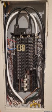
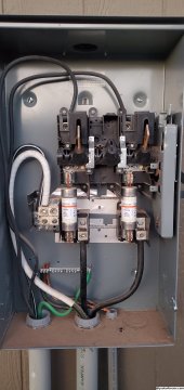
Can we have a photo of the 200A service disconnect and the breaker panel and how these are wired?