diy solar

diy solar

Really need some help or advice

If it were me, I would only wire the generator to the 6548 inputs, and also to a chargeverter, and not have the generator feed anything else. Then you don't need any external ATS, since 6548 already do ATS.

I think with the Predator it might not be clean power which could affect the inverters.

I'd prefer a Chargeverter off the generator.

This is how I am setting up my system. The generator will only be optionally wired to a small 2-breaker box, where one breaker feeds the AC inputs on the inverters (with feed breaker turned off probably forever), as I plan to use only my 4x 48v AIMS battery chargers (on the other of the two breakers) to charge batteries directly, but if I have a failure on my battery chargers, I can turn on the other breaker from generator to the AC input on the inverters and charge that way.

I don't see any reason to wire a generator directly to the load panel, since the inverters already have bypass mode for that.
It would depend on how clean the generator power is.
 
What is the breaker with the yellow hold down kit?
I assume that's the breaker with the lock? It goes to my well. It's actually the only 240v in use. The other two are to the outside AC breaker, unused, and to a dryer plug, unused as I have a gas 120v dryer.

What do you mean by clean power from the generator?
 
I think with the Predator it might not be clean power which could affect the inverters.

I'd prefer a Chargeverter off the generator.


It would depend on how clean the generator power is.

Yeah, that's exactly what my setup is, except I have 4 AIMS 18.75a battery chargers which will likely work forever, but if they fail, or if the inverters fail, I can turn on the other breaker to connect the generator to the inverter AC input, where the inverters can run in bypass (whether they are able to charge batteries or not, they will still bypass and pass through power directly to your house breaker box..
 
Last edited:
What do you mean by clean power from the generator?


So if the gen power is not precisely @ 60Hz or inside acceptable voltage levels, the inverter will not use it for charging. If that happens, you should still be able to turn off the inverters (put them into bypass) and should just pass through the gen power through it, but can't charge batteries with it.
 
Last edited:
So if the gen power is not precisely @ 60Hz or inside acceptable voltage levels, the inverter will not use it for charging. If that happens, you should still be able to turn off the inverters and should just pass through the gen power through it, but can't charge batteries with it.

That's one reason why I am going with the option of standalone battery charger(s), because they are not picky about the input Hz or voltage, my AIMS chargers say in the Specs:

Input Voltage96-145VAC full performance
70-96VAC automatically de-rate to 50% of full load current
Frequency40Hz to 70Hz


So the generator can run like crap if it wants and still get through a battery charge cycle or two, until I get the generator fixed better...
 
So if the gen power is not precisely @ 60Hz or inside acceptable voltage levels, the inverter will not use it for charging. If that happens, you should still be able to turn off the inverters and should just pass through the gen power through it, but can't charge batteries with it.
Ok, I see. I use the clock method, but my generators average about 60hz over 12 hours. My current generator is at 55hz, that's how I know it's going bad.
 
I assume that's the breaker with the lock? It goes to my well. It's actually the only 240v in use. The other two are to the outside AC breaker, unused, and to a dryer plug, unused as I have a gas 120v dryer.

Why the hold down?

What do you mean by clean power from the generator?
Sine wave, frequency and voltage regulation. If any 3 are off, not so good for electronics long term.

The Chargeverter eliminated the problems with running generator power to inverters. It is a good solution plus, the generator will be more efficient as all power will go to the battery bank instead of the generator running with small loads.
 
55Hz means the RPM is too low.. I use a simple Kill-A-Watt EZ meter to set on Hz to adjust the generator governor (rpm control)..
I have one and should learn to use it, but the old hippy methods are hard to break.

Looks to be a lock on second look, I assume so the dryer won't run with other loads present.
It's incase it flips, something is seriously wrong and I don't want anyone to reset it. Its the only 240v in use and the well has it's own system, it should shut down there. The lock and breaker was installed by the well electrician.

So, I should just remove the ground in the secondary inverter? And I should leave the bond in the generator? I do know there is suppose to be two g-n bonds in the house somewhere. There should be one at the waterheater and one somewhere else, by code.
 
I have one and should learn to use it, but the old hippy methods are hard to break.

The Kill-A-Watt is super easy to use for Hz reading. Just plug it into the power source, hit either the up or down arrow selector until you see the Hz shown in the display, and that's it, not any harder than that.
 
So, I should just remove the ground in the secondary inverter?

Remove the bonding screw in one inverter. The ground rod at the breaker will suffice to bring the G side to earth potential.

And I should leave the bond in the generator?

Leave generator bonded, there is no N-G bond in any of your panels. As for the inverters, only one should have the bonding screw which enables N-G bond under inverter power.

I do know there is suppose to be two g-n bonds in the house somewhere. There should be one at the waterheater and one somewhere else, by code.
There should only be one point that is N-G bonded. With 2 N-G bonds present, there will be objectionable current that will be shared by N. Remove any other bonds.

When the transfer switch is turned to generator, the system relies on the generator N-G bond. When under inverter power and transfer switch set for inverter, the system relies on the inverter N-G bond.
 
Leave generator bonded, there is no N-G bond in any of your panels. As for the inverters, only one should have the bonding screw which enables N-G bond under inverter power.

There should only be one point that is N-G bonded. With 2 N-G bonds present, there will be objectionable current that will be shared by N. Remove any other bonds.

When the transfer switch is turned to generator, the system relies on the generator N-G bond. When under inverter power and transfer switch set for inverter, the system relies on the inverter N-G bond.
It's highly possible I'm wrong, and there is no bond. The person I'm asking is a friend and retired electrician. My house electrician won't call me back because he owes me money. The inspector that did my final told me that my permit covered the rest. It's possible he only wired the breaker and left everything else up to who was doing the live connection. Is there any easy way to test for one? And if the generator and inverter are bonded and on the same n-g poles, it won't be an issue?

Also to add, I just realized my hot water heater is gas, so it has no electrical connections. It wouldn't be possible to have one there for me.
 
When the transfer switch is turned to generator, the system relies on the generator N-G bond. When under inverter power and transfer switch set for inverter, the system relies on the inverter N-G bond.
Your correct, my house has no bonds. I took photos of all the locations my friend said they should be in, and none are connected or set up.

Called my inspector, he said by code I can only have one ground neutral bond in my set up, and it HAS TO BE, his emphasis, done in the transfer switch. So how does this change things? I know how to do the the transfer switch. But do I now remove all other bonds?

So you'd need to unbond the N-G in the generator (generator gets grounded like an appliance in that particular implementation), unbond it in both inverters.
 
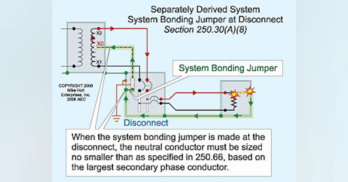
There are a couple of different ways to set it up, depending on whether you are going to consider the generator as a separately derived power source or not...

More info:


Since we can only have one N-G bond based on NEC and safety, if the generator has an N-G bond, then while it is connected to the house system, all other N-G bonds must be opened during that connection, once the generator is fully disconnected (including N and G) from the system, another N-G bond closest to the power source needs to be re-established, through the switching mechanism.

The purpose of the N-G bond is to provide the best ground return path back to neutral of the power source, so as an over-current short will cause enough current to flow to trip the breaker and remove the threat (since an Earthing ground rod is not considered a reliable low resistance path back to the power source). And we only want one so we don't get objectionable neutral current flowing through a ground wire between 2 bonds...
 
Last edited:
There are a couple of different ways to set it up, depending on whether you are going to consider the generator as a separately derived power source or not...

More info:


Since we can only have one N-G bond based on NEC and safety, if the generator has an N-G bond, then while it is connected to the house system, all other N-G bonds must be opened during that connection, once the generator is fully disconnected (including N and G) from the system, another N-G bond closest to the power source needs to be re-established, through the switching mechanism.

The purpose of the N-G bond is to provide the best ground return path back to neutral of the power source, so as an over-current short will cause enough current to flow to trip the breaker and remove the threat (since an Earthing ground rod is not considered a reliable low resistance path back to the power source). And we only want one so we don't get objectionable neutral current flowing through a ground wire between 2 bonds...
Separately derived means powering the system somewhere not directly with an off grid source like using it on the AC input, correct?
 
Separately derived means powering the system somewhere not directly with an off grid source like using it on the AC input, correct?


Take from the thread below:

"Unless you are switching the neutral, a generator is not a Separately Derived System.
See 701 for required standby systems"


Read more about it:
 
Take from the thread below:

"Unless you are switching the neutral, a generator is not a Separately Derived System.
See 701 for required standby systems"


Read more about it:
Well that made it extremely clear. I cannot do a separately derived system with my current setup, in regards to my generators. I have nothing currently to switch my neutral.
 
Well that made it extremely clear. I cannot do a separately derived system with my current setup, in regards to my generators. I have nothing currently to switch my neutral.

You can check in the manuals for the generators and see if they indicate how to disable the N-G bond on them, or at worse case ping the manufacturer, or Google around and see if you can figure out where the bond is, if exists. Have you confirmed already if they have the N-G bonding or not from the factory?
 
Back
Top