Warpspeed
Solar Wizard
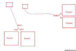
Try fitting diodes where you join panels. See if it makes any difference ?
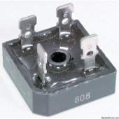
What I use are the thirty five amp metal diode bridges.
The metal case is insulated from the diodes, and you just use two of the four internal diodes.
Each panel positive connects to one of the ac terminals, and the + output of the bridge is the output.
The -ve terminal is not connected.
It will probably run quite hot, but you can bolt the metal case to one of the panel mounting rails as a heat sink.