diy solar

diy solar

JK-BMS-CAN with new Cut-Off Charging Logic (open-source)

So the MQTT solution by @Der_Hannes was just a temporary fix for his use case ? It's not the way forward ?

RS485 or CAN for multiple (inter) BMS communication could be nice, but I don't have much experience using those protocols.

I guess it's just a matter of setting up several registers on the master controller (the one talking with the Inverter) say up to 32 registers sets (for up to 32 batteries) where each register contains ALL the data that is being sent out by the slaves (so each register set is actually maybe 99 registers to store all cell voltages, current, power, energy, etc).

Multi-BMS via MQTT is a code developed by @Der_Hannes . It works but using WiFi and MQTT to receive and process information is a solution with a high risk of failure and problems. This is @Der_Hannes 's solution but the one we will use in the future. He is working with us for future multi-bms code.
 
Multi-BMS via MQTT is a code developed by @Der_Hannes . It works but using WiFi and MQTT to receive and process information is a solution with a high risk of failure and problems. This is @Der_Hannes 's solution but the one we will use in the future. He is working with us for future multi-bms code.
Personally, regarless of CAN or RS485 implementation (I'd still prefer 1 JK BMS to be on 1 ESP32 - Just for easier modularity), I'd start defining an EXCEL Sheet with Register Numbers and Battery Assignment / Value on the "Master". Basically to map all the current values you have right now on each ESP32 device.

Not sure about CANbus registers though. I can understand RS485 better for the time being.

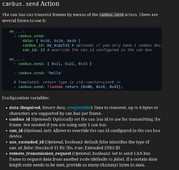
can_id and data_frame ... can_id for me is the node_id, while data_frame could contain the register address.
Alternatively can_id can contain both the node_id and the register address (with proper decoding done on the master side I guess), and data frame only the data ? Not sure.

1712137121387.png

RegisterUse
Description
00001MasterRequested Charge Voltage
00002MasterRequested Charge Current
......Equivalent SOC
00999MasterEquivalent SOH
01001Battery 01Cell Voltage 01
01002Battery 01...
...Battery 01Current
01999Battery 01Power
02001Battery 02Cell Voltage 01
02001Battery 02...
...Battery 02Current
02999Battery 02
......
32001Battery 32Cell Voltage 01
32002Battery 32...
...Battery 32Current
32999Battery 32Cell Voltage 01
 
@silverstone

I don't have time to discuss the CAN bus at the moment. I myself already have an Excel sheet that I must update with all the data expected by the smart_bms.yaml and smart_bms_combine.yaml components. I have to produce documentation on this subject on the operating principle of the packaged version and how the different components are connected to each other. I developed it so that a component can be replaced by another component in order to be able to use several multi-bms approaches.

As soon as the documentation is finished I will share it.
I can understand .. It's difficult to do Thinking/Logic + Coding + Documentation and keeping all of these in sync, especially when everything (most likely) keeps changing all the time until you "settle" on a given approach (until that changes again).

So basically it's either wait or potentially do double work (fork) :(.
 
This might be a noob question, but does atom s3 lite have the ability to get data from the JK BMS over bluetooth instead of a wire connected to the GPS port?

Also, I had to flash the firmware OTA instead of cable in order for this to work ( some processes appeared to loop after cable flash )

Here are now some random output :),

[16:15:27][D][canbus:035]: send standard id=0x359 rtr=FALSE size=8
[16:15:27][D][sensor:094]: 'jk-bms-can Auto Charge Voltage': Sending state 0.00000 V with 1 decimals of accuracy
[16:15:27][main:1358]: Alarm Status : NoAlarm
[16:15:27][D][text_sensor:064]: 'jk-bms-can Charging Status': Sending state 'Wait'
[16:15:27][D][sensor:094]: 'jk-bms-can Requested Charge Voltage': Sending state 52.80000 V with 1 decimals of accuracy
[16:15:27][main:1404]: send can id: 0x351 hex: 10 2 0 0 0 0 ff ff
[16:15:27][main:1405]: Charge Status : Wait
I'm using mine with BLE without issues. I had sent the link to my file
 
Ooh, that make sense.. Right I had some issues getting that to compile, but I will give it another try!

Thanks!

Edit: Like your username, I used to race cars on the silverstone circuit :) Good fun!
Maybe I should just switch to "luckylinux" as I use everywhere else. Maybe the Administrators can change that everywhere with some REGEX Search+Replace feature :) .

About the compile yeah, the helper script is for GNU/Linux (Debian/Ubuntu mainly since it automatically installs the Python venv module).

Nothing forbids anybody to convert this to cmd or Powershell scripting though.

It's just a helper to setup the build environment.

In a normal life you should only need "esphome run XXXX.yaml". Maybe do a "esphome clean XXX.yaml" if you had issues when (re)building before doing "esphome run XXX.yaml" again.

EDIT 1: but of course you need to manually activate that venv and change directory to the build path etc, when all of this is done by my helper script.

But if you install esphome with pip on system level (that's a WHOLE other discussion with potential conflicts, that's why Debian/Ubuntu do NOT allow that anymore by default) it could be a bit easier.
 
Have it up and running now. Too bad I ordered the cables for the GPS port yesterday, oh well 😁

Yes, I did notice your CAN settings where different from mine, Thanks!
Well it's better if you use the wired connection to be honest, it is more reliable IMHO.

BLE isn't that bad, but I'm also losing connectivity from time to time (approx. 6 hours every 4 weeks or so). I also bought the JK RS485 adapter so in my case I'd have to use the RS485 M5 Base for the Atom S3 Lite.

According to Sleeper85 GitHub Repository this should be supported:
1712170768630.png


@Sleeper85 , @MrPablo: what happens actually if there are no more (valid) data coming form JK BMS to ESP32 Controller (because e.g. of unreliable BLE connection) ? Does the Controller just go into a "Safe" operating point (e.g. Float and maybe only half the operating current), does it trip the inverter (Deye BMS_Err-Stop) or what else ?

EDIT 1: @RostadKatt: be VERY careful with the UART connection. One pin of that connector is VBAT (56 VDC) if I understood correctly !!! That is NOT connected according to the schematic to the ESP32 (for obvious reasons). Just make sure you don't mistakenly connect it ...
 
Last edited:
Hi,
I think we should not debate on SOC issue any more, It can be solved already:
+ If JK SOC reported 100% at 3.35 or somewhat too low (less than 3.4 while charging) >> it need to keep charging, it can still absorb: in my case, I report to Inverter 98% (Sleeper85 use 99%) as Inverter sometime stop charging at 99%. and it can take remarkably more energy and SOC will reset at 100% at the new energy level!
+ If JK SOC report 0-10% at 3.2V or higher or suddenly drop to 0 in no where. This need a refreshing discharge. Keep discharging till voltage drop to 3.1V (with moderate discharge current) and then charge to full (as closer to 3.45 as better).
This is how I did and we will not have to touch the jk Bluetooth app anymore.
Best

Here is the new code regarding the calculation of SOC.
Keep in mind that this code should work can import the battery chemistry used LFP, Li-ion or LTO so it cannot use a fixed voltage value as you suggest.
Furthermore I don't want to change the SoC of the JK-BMS too much, when JK-BMS is well calibrated it is not so bad.

The code below will send the actual SOC of the BMS(s) from 1 to 98%
Only 0% and 100% are corrected to correspond to reality.

YAML:
  # +--------------------------------------+
  # | Battery State of Charge (SOC)        |
  # +--------------------------------------+
  - platform: template
    name: ${smart_bms_name} Battery SOC
    id: ${smart_bms_id}_battery_soc
    unit_of_measurement: "%"
    device_class: battery
    update_interval: ${smart_bms_update_interval}
    lambda: |-
      float soc = id(${smart_bms_id}_state_of_charge).state;
      float min_cell_v = id(${smart_bms_id}_min_cell_voltage).state;
      float cell_uvpr = id(${smart_bms_id}_cell_uvpr).state;
      if (min_cell_v <= cell_uvpr) return 0;                       // Real 0% Sending 0%
      else if (soc < 1) return 2;                                  // False 0% sending 2%
      else if (soc < 99) return soc;                               // SOC < 99% => Sending BMS SOC
      else if (id(${smart_bms_id}_eoc) == true) return 100;        // End Of Charge => Sending 100%
      else return 98;                                              // Otherwise => Sending 98%
 
@Sleeper85 , @MrPablo: what happens actually if there are no more (valid) data coming form JK BMS to ESP32 Controller (because e.g. of unreliable BLE connection) ? Does the Controller just go into a "Safe" operating point (e.g. Float and maybe only half the operating current), does it trip the inverter (Deye BMS_Err-Stop) or what else ?

This is a very good question and I'm just testing it in the new multi-bms version when no BMS sends its data.
 
But actually @Sleeper85, I guess it should be quite easy to test. Just try to turn off BLE via the switch (or remove the UART cable in your case) and see what happens tomorrow early morning when there is not too much sun. Then monitor Requested Charge Voltage, Requested Charge Current, Requested Discharge Current.

Or is there another way to poke at it ?

EDIT 1; sensor timeout property might be useful (will send NaN values if value cannot be fetched). Then maybe when you do Automatic Voltage/Current Control check if it's a Number (Float) or if it's NaN, in which case default to a "stable" state.


Other alternative is for BLE to use ble_client with the method on_disconnect and set a flag to a variable that you check in Automatic Voltage/Current Control.


EDIT 2: in my specific case, the ESP32 indicates "Offline" in the "Error" field of the JK BMS MQTT Field (at least it used to do it with the Syssi esphome-jk-bms code). I assume this means "BLE Connection Lost", because apparently the JK BMS itself didn't turn off, since charge/discharge was still working.
 
Last edited:
Is it possible to filter out / remove the "[D]" ( debug ) information that continuously gets sent to the web server?
Don't you have this in your config file ?
Code:
logger:
  hardware_uart: USB_SERIAL_JTAG
#  level: DEBUG # For Debugging only
  level: INFO # For Production

Make sure level is NOT set to DEBUG !
 
Don't you have this in your config file ?
Code:
logger:
  hardware_uart: USB_SERIAL_JTAG
#  level: DEBUG # For Debugging only
  level: INFO # For Production

Make sure level is NOT set to DEBUG !


My bad, accidently commented that part out. o_O

Debug is gone, and now these [W] arnings caught my attention.

21:39:51[W][component:232]Component esp32_ble took a long time for an operation (127 ms).
21:39:51[W][component:233]Components should block for at most 30 ms.
 
Back
Top