diy solar

diy solar

Building the sickest ® VAWT ever. Brilliant minds unite please!!

magnesium oxide powder has arrived. but that lady with a rather large contour is still not done singing.
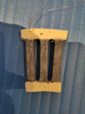
This time I will test if only adding iron powder to the coil legs will do what I think it should be doing.

When everything is filled with iron powder like previous test coils, not only the coil legs, then the field will also find easier paths at the end through the coil ends. where the wires do almost nothing.
I will see if this hypothesis holds up or not.

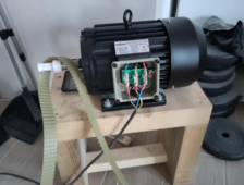
Now for the motor. The slowest I can make it run is at 1.5Hz. any lower and one can detect a non uniform rotation.

But with this motor that 1.5 Hz means like a million times too fast for the PMA.

I am breaking my head to get the PMA to rotate at 3.7 Hz as baseline. Working our way up from there should be not a problem at all as that simply means increasing the motor speed by tiny amounts of Hz. the resolution there is 0.01 Hz.
 
I realy do not like this.

please just add here with what you concluded and then link to the source you used to reach your conclusion.

If we allow for this to be acceptable then it will be all to easy to flud threads via means of overflow. (DOS)
 
yesss!! nailed it again.

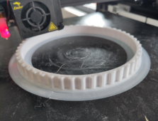
look how I was able to reduce the tooth count from 20 to only 7 with the aid of some 3d printing mastery. (thank you Gary!)

1712252782260.png
this will make it less cumbersome to print a T10 pulley for the PMA as to have it rotate at originally intended speeds when the motor is at minimum speed.

Because for all I know yet I need to increase the teeth count on the driven pulley by 2 as opposed to the driving pulley teeth count if I want to decrease the speed by 2.

Well, I am not even sure yet but I think we will be needing 7 teeth times 10 if we are ever going to arrive at the intended 3.7Hz baseline.

Now just imagine a 70T T10 pulley. There are very few entry level printers that can actually print it in one go. I think even mine can not.
 
my final struggle attempt to go into the books as Einstein.

But I am not holding my breath though as I have long time known already life never dealt me the right set of cards to play with.

1712253639778.png
the idea is this time the field has no where more permeable to go but though the legs.
Not like before in where parts of the field could have been persuaded to go through the numb parts (non contributing) of the coils. aka the coil bends.

Lets see in a day or 2 if this pans out or not.
 
Last edited:
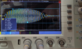
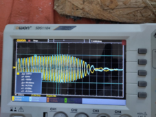
I give up. even this most recent coil with only the legs filled with iron powder simply does not produce an voltage enhancing effect.
if anything it actually helps the field to circumvent the coil wires as it now can wiggle around the wires rather than through them.

Blue channel still is the plain coil.

1712305376396.png

I am at the end of my whits now and can make no sense of earlier tests that suggested the opposite would happen. In where I added bars of iron powder to a magnet pair and measured the field in the middle. It was soo much higher than without the iron powder bars.

Ahh well it is actually beneficial in a way to have to abandon this route as now installing the coils will be much easier when not so violently attracted to the rotors.
And the magnesium oxide powder is in like I mentioned but have yet to demonstrate it is actually effective for heat dissipation purposes.
 
NOOOOOO.

even though I managed to reduce the teeth count on the motor from 20 to 7 I still end up needing
135 teeth on the PMA to have it rotate at the intended baseline speed which would result in 3.7HZ

135 teeth would mean a diameter for the pully of a whopping 428mm. That is not something I can print in one go and even if I could then the time it takes will be astronomical.

@justgary would you be ok with me going for a baseline speed of 14.8 Hz which is 4 times 3.7Hz. As it is actually the intended speed at which the PMA should run while in service.
Now in order to still be able to demonstrate the (non)linearity of the voltage production while increasing the speed I think it should not matter what baseline speed we use yes?
I intend to make this graph you asked for the best as I can but if somehow that means I have to start at 3.7Hz then I need to think of a gear system to work around this limitation of the motor that can't run smooth any slower than it does now.
 
Last edited:
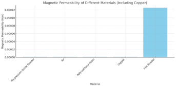
some more data, which is unconfined yet as it is from my (un)trusty ai friend.

1712308483472.png

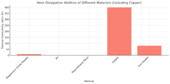
I am not sure if this magnesium oxide powder will go do wonders for heat dissipation when I look at the below graph

1712308509680.png
Let us assume these figures were arrived at correctly. Please do not actually do that but let us just assume for now.

What does this tell us?
 
ok i figured it out. I think.

using magnesium oxide we will enhance the thermal conductivity by less than 20 times as opposed to plain old poly resin.

But here comes the kicker!!
As magnesium oxide is diamagnetic, which means it tends to become magnetized in a direction opposite to that of the magnetic field applied to it, but only very weakly so. Diamagnetic materials are characterized by their tendency to be repelled by a magnetic field, in contrast to ferromagnetic materials, which are strongly attracted by magnetic fields.

Well this might mean it can help counter act the field/attractive nature of the iron filled cores to be added later.

Ok it is confirmed. I can start real world tests to actually see if this Ai is more of a help than it is a hindrance.

I just do not hope this counter field will negatively influence the field produced (more than the reason for adding such an agent will bring for maximum power potential of the coils) by the electromagnets. But future tests will tell us.
 
Last edited:
I have got to address this again.

Now You know my opinion of our friends in the east. Most of them are dumping (potentially hazardous to human life as well) electronic waste to our markets.
And they are not solely at fault also if we think of it. No it are also consumers like me that are still buying. and we keep buying. and then buy some more.

But there is a distinction I would like to make in the defense of great companies from that region.
Some of them are really at their A game when it comes to applying great technologies. Sure we have the ever lingering IP theft issue that hangs over us like a dark cloud but that only seems to enhance our purchase willingness.

Just please do not barge inhere without a clear (well at least me me at least) message. I looked up your posting history and that is what made me post this post on my thread.

Look, you might well have intended to be supportive and not just found a new way to insert some advertisement. I just will never know as I stopped reading your link after the first paragraph.

So please elaborate what it was you were trying to add to our mission ok?
 
if anything it actually helps the field to circumvent the coil wires as it now can wiggle around the wires rather than through them.
INSANE!! this made me think of one last experiment I can try.

I will motivate why.

You see that if you place a tesla meter probe in the middle of an iron filled structure you get almost no field. This I think is because the field happy gets circumvented around the chamber in where said probe resides as it is a tube of PLA with an air core.

But when I use 2 iron powder boxes attached to a single magnet pair then there is a aig gap between them in the middle. Now I can measure an intense field increase.

Now what if now NOT fill the 4.5mm coil it self with iron powder so that the fieldlines might be persuaded to wiggle around the coil wires rather than through them. I only fill the 2 remaining sides with powder.
Then in essence we have a similar setup to the 2 powder boxes with which I can demonstrate a field increase.

ahh now I know. this makes no sense as then one can simply opt to reduce the distance between the rotors if the actual thickness where the wires reside is but 4.5mm

choices choices. why have I not been preparing early in life!!

well tI really would like to settle at a 17mm spacing as that gives the best distribution of the field between the rotors and the adjacent magnets as far as I was able to tell.
Also as one phase is rather long in wire length then I will need to combine several coils of 0.4mm in parallel to reach a desirable amp level fot the benefit of the electromagnetic field (as my other sizes might not be sufficient in terms of length available). So there goes this 4.5mm spacing idea. it will be several times that.

So in the end of the day I think it is safe to conclude that the benefit of iron powder in coil legs had not been demonstrated. In fact we have discovered counter evidence.
 
Last edited:
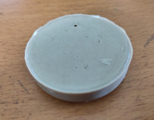
please bear witness to my first ever magnesium oxide powder cast.

1712328306210.png

I did not take any notes so I have no idea on the percentage.
Also these air bubbles seem to be only on the surface. the bottom of the casting seems to be totally without.

i do not know yet of a method on how to assess if there are bubbles in the middle of the casting.

Now I can consider getting a vacuum chamber but then only if it is established that this powder does indeed help to improve the thermal conductivity as opposed to just plain old resin.

{1}maybe just any old sanding machine without the paper on it and then let it vibrate on the curing casting. it might get the bubbles out. I should go and double check the abrasiveness of this element else risk ending up in the same pickle we were before Gary warned us of begging for shorts.{/1}

and as per usual I am open to suggestions of course
 
Last edited:
coils are in the making.

the composition will be 3 x 0.4mm x 35 winds spread over 31 coil legs per phase. we will thus end up with 9 times this rather large coil you see here on the photo.

1712333972524.png

Please excuse my kid for making a mockery of my punching bag.
this is not subliminal advertisement.
 
and please excuse me for making a workshop out of my gym.

even though. I have lost a metric ton of weight and am now since years steady. not at all light of nature but fit and steady in terms of weight.
 
MgO should be an exceptionally good electrical insulator. It is used inside heating elements for ovens, etc. to keep the wire from shorting against the outer case.
 
Ohh WOW!!

Stacking layers of wires is a bad idea if one intends to run them in parallel.


1712525450016.png

This is not to say that the "wire in hand" concept which I still do not understand but has been presented several times to me before, does not make any scene.
No I think the combining of wires should be done in a Litz wire sense in case we want to combine the area each wire can contribute. Stacking of "things" is a whole nother level of beast mother nature is not keen to talk about. It is for people like me to make sense of it.
 
Last edited:
I give up.
of course not this early.

as time goes on I get inspired to try more and, in many ways less outlandish mechanisms, to get this agreed on or not.

You see then when we stack in parallel different of voltage sources in vertical (layers of coils) then there will be yet to be confirmed to me voltage negative interference. My stance is. Do not do it!!
It just does not make any sense when we would like to include mother nature and her laws of which I will never know anything.
 
Last edited:
Back
Top