diy solar

diy solar

Input and output swapped on a Victron Smartsolar 75/15

pointless_cog

New Member
Joined
Apr 6, 2024
Messages
2
Location
NSW Australia
Hi,

First time poster, so apologies if this is in the wrong spot!

We are developing a portable solar charging system, which has a Victron SmartSolar 75/15 between the panels and a battery system I have no control over (long story). Anyway, the MPPT will be housed inside a clear lidded, polycarb box, along with the required breakers, fuses, etc. Unfortunately, and again outside of my control, both the solar input connectors and the battery system outlet connectors are going to be MC4.

Whilst I will be labelling these extremely clearly, the users of this system could plug the solar in the output side and the battery in the input side of the MPPT.

I'm wondering if anyone can give me some guidance on what might happen if this swap occurred?
 
24V battery or 12V?
Honestly, on the output side, once the panel voltage exceeds the maximum battery voltage, the SmartSolar will likely be damaged permanently.
On the input side, the battery voltage may be too low to trigger any mppt sweeps as if they were panels.
This will be a cross your fingers kind of thing.
I know you have no control over this, but big labels saying BATT and PV can’t hurt.
Even worse would be if they cross connect + and - so both the panels and battery are split between input and output.
 
Yeah, I would get some colored tape, and bundle the PV pairs one color, and the battery connectors a different color.
 
I'm wondering if anyone can give me some guidance on what might happen if this swap occurred?
I spend a lot of time trying to guest proof my systems. They will always not understand or not follow instructions, no matter how I label or put colored tape on.

If you need to stick to MC4s, “Guest Proofing” won’t be possible. Can you make one set of connectors Anderson plug and the other connectors MC4? Both of those connectors make it impossible to reverse polarity, and a different connector on each will prevent plugging the wrong device in.
 
Also, since MC4 connectors aren’t designed for easy disassembly, you should get some Anderson connectors and make up adapters with 50A Anderson’s on the battery side, and 45A Anderson’s on the PV side… then it is much simpler to disconnect and reconnect for whatever reason, and there will never be a mix up.
 
I spend a lot of time trying to guest proof my systems. They will always not understand or not follow instructions, no matter how I label or put colored tape on.

If you need to stick to MC4s, “Guest Proofing” won’t be possible. Can you make one set of connectors Anderson plug and the other connectors MC4? Both of those connectors make it impossible to reverse polarity, and a different connector on each will prevent plugging the wrong device in.
Like minds…
 
I'm wondering if anyone can give me some guidance on what might happen if this swap occurred?
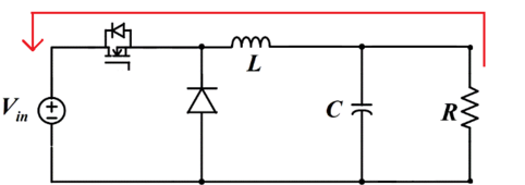
Probably no damage but you assume all liability if you want to try it. It's a buck converter. Putting higher voltage on output will make current flow back to input through inductor and mosfet body diode. So your solar panel will charge lower voltage battery without MPPT being able to interrupt or modify the current. Basically like connecting solar panel direct to battery.
buck-conv.png
 
Hopefully that output cap is rated for the panel voltage it will see. Victron is pretty conservative, I’m sure they built in some margin.
 
Good point. Vicron could have installed 35V caps inside 75/15 since it's never supposed to see above 30V out because it's designed for up to 24V battery. Placing 50V caps makes little sense.
 
Good point. Vicron could have installed 35V caps inside 75/15 since it's never supposed to see above 30V out because it's designed for up to 24V battery.
I couldn’t find a max battery voltage in the manual or data sheet, but equalization runs at 32.4V, so it has to survive that.
Standard factor of 2 conservative margin means maybe 63v caps (being optimistic for the OP)
 
Thanks for the ideas, agree a different, incompatible connectors on input/output makes this problem disappear, but the users are supplying the cabling, another thing we have no control over 😳

AntronX, thanks for the explainer. Fingers crossed for high voltage caps!

Big labels, lots of training, and a huge "you break it, you bought it" disclaimer I think!

I will test this 'user error' before it goes out the door 🤞
 
I will test this 'user error' before it goes out the door 🤞
I would test it by connecting 10Kohm resistor across PV input and measure voltage across it. If you measure your battery voltage across that resistor then it should confirm what I described. If no voltage then there is another diode or mosfet switch in series internally with input. Now that I think about it more there has to be another series switching device because at night PV voltage reading drops to zero and it would read battery voltage otherwise.
 
I would get four different colors of nail polish and mark them in appropriate pairs. I’d also clearly document the failure modes and responsible persons and tuck a copy of that document into the box.
 
Anderson connectors of different colors so they won't allow wrong pluggin.

Electrically - a 2/4 pole contactor such that backwards voltage disconnects the inputs and sound an ear piercing alarm and light until the backwards set is removed. This way even if they hook things up with everything off as soon as they turn it on it disconnects. And do all the labeling.

Maybe a three position switch to turn on. OFF-TEST-ON. ...test sets the contactor off if a reverse voltage detected. Maybe charge a large cap that keeps things off until put back in the OFF position. This before the box blows up. Probably require an internal battery to do it right.

@timselectric can talk all about contactors
 
Last edited:
Would adding a meaty Schottky diode in series with the battery output connector mitigate the issue?

It would of course affect the charging profile somewhat, but not as much as letting out the magic smoke from an incorrect connection.

Do note that testing a single unit with an incorrect connection and "getting away with it" is not a guarantee that every example of MPPT and battery will "get away with it".

May I suggest getting some proper engineers involved in the design? No engineer worth his salt would "design" something like this!!


Says he, noting that his new Seplos BMS has 3 x 4 pin connectors next to one another for switch, display and "something else" all interchangeable. Luckily plugging the display into the "something else" plug doesn't kill anything.
 
You can connect thr
Also, since MC4 connectors aren’t designed for easy disassembly, you should get some Anderson connectors and make up adapters with 50A Anderson’s on the battery side, and 45A Anderson’s on the PV side… then it is much simpler to disconnect and reconnect for whatever reason, and there will never be a mix up.
Could do something like red SB50 connectors for solar and black for battery connections or something, the different colors won't physically intermix.
 
24V battery or 12V?
Honestly, on the output side, once the panel voltage exceeds the maximum battery voltage, the SmartSolar will likely be damaged permanently.
On the input side, the battery voltage may be too low to trigger any mppt sweeps as if they were panels.
This will be a cross your fingers kind of thing.
I know you have no control over this, but big labels saying BATT and PV can’t hurt.
Even worse would be if they cross connect + and - so both the panels and battery are split between input and output.
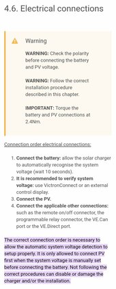
Per the manual it's ok to connect the pv prior to the battery on Victron SCCs. The proviso being that on first power up, the SCC uses that to set its default charging voltage (12, 24, 48V, with 36V requiring manual setting), and that's when you need to connect battery first (or use Victron connect or ve direct to adjust prior)

Screenshot_20240422_060958_Chrome.jpg

 
I use XT90 connectors. You can buy them with 10awg pigtails already soldered in and just use crimp connectors.
xt90
 
Back
Top