diy solar

diy solar

Paralleling two 12 panel arrays before MPPT 1 on 18Kpv?

Ubby

New Member
Joined
Jun 5, 2022
Messages
21
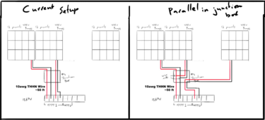
Rather than try to run more cables in my conduit down to my 18kpv, I'd like to parallel my 2 arrays in a junction box and then use the leftover run to attach more panels to it. The 2 arrays are already used on MPPT 1, and I heard putting them in parallel before the inverter is just fine, but want to confirm. Can I just use wire nuts to parallel the arrays? Attached is a picture for reference.
1712850790069.png
 
Per your notes on the drawings, 2 parallel strings is only 18A and the distance is less than 50'. This is well within the recommended limits of 10AWG wire.
 
Per your notes on the drawings, 2 parallel strings is only 18A and the distance is less than 50'. This is well within the recommended limits of 10AWG wire.
Thanks! That's what I figured, but wanted to verify! Any concerns with paralleling with large wire nuts?
 
No. The max amps for mppt1 on the 18kpv is 25a.

Edit - sorry I see the 3rd array going to mppt2. 🙂
 
Any concerns with paralleling with large wire nuts?
Is there any reason you don't want to make a proper connection?

Fixed:
24 panels x 400W = 9600W
Using wire nuts here is like duct taping wings onto an airplane.
 
Last edited:
Is there any reason you don't want to make a proper connection?

24 panels x 400W x 9A = 86,400W
Using wire nuts here is like duct taping wings onto an airplane.
Mainly the size of the junction box. I'm certainly open to other suggestions.
 
Wire nuts freaked the hell out of me when I first moved to the USA, but I now appreciate them for what they are, a damn fine cheap and simple connector that works astonishingly well.
I seriously challenge anyone to find a better method to connect multiple wires together.
 
Is there any reason you don't want to make a proper connection?

24 panels x 400W x 9A = 86,400W
Using wire nuts here is like duct taping wings onto an airplane.
I believe your math is off here. It's 2 arrays of 12 panels at 9 amps at 400 volts. 2 arrays of 3,600 watts.

So in parallel they'd be 7,200 watts max.
 
Okay, so you want to make wire connections.

First is location: dry or damp or wet.

Second is wire gauge. Some wire connectors will easily allow the connection of different gauge wires, others not so much.

Third is choice of splice connection.

Choices:

Wire nut = dry location. Wet location are available but I would avoid these except on the ground wire.

Butt splice = dry or wet location. Uses a crimp tool for end to end splicing. If not done properly, can be pulled apart. Wet location will require a waterproof heat shrink material with thick walls to be applied over the splice.

Butt Splice connector with screw down terminals. For dry or damp areas if properly insulated. These are not insulated, but make secure, easy connections without crimping. Must be insulated after connection is made. Heat shrink tubing, other insulating tapes. Harder to service after the fact.

Terminal strip. Dry location. Screw the ends of the wires to the connection on the terminal strip.

Split bolt: dry location. Requires rubber tape for insulation covered with electrical tape.

NSI Polaris wire connectors. Dry location. Insulated, easy to put on and take off for future maintenance. Includes silicone corrosion protection. This is a UL listed item. The linked amazon product above I do not believe is UL approved. Furthermore, this item can be had for about $12 each. Check a local City Electric in your area.

NSI Polaris waterproof wire connectors. Damp, wet and briefly submerged situations. An EPDM rubber coated wire connector that can be easily removed and put back on. Lots of corrosion protection.

Electrical epoxy resins for encasement. Dry, damp, wet underwater locations. 3M Scotch and other companies make these products. You create your splice and then encase the splice in a mold (may be provided as part of a splice kit) and the epoxy resin hardens and is waterproof. Cannot be serviced.
Super helpful! Thank you!!!

These connections will (hopefully) be made within an existing outdoor rated 2 gang metal junction box. Everything is already flowing through there. I'll do my research on these options.
 
Super helpful! Thank you!!!

These connections will (hopefully) be made within an existing outdoor rated 2 gang metal junction box. Everything is already flowing through there. I'll do my research on these options.
Remember, everything outdoors that is metal must be grounded. This means panels, racks, conduits, boxes, etc. Anything outdoors that is not metallic, like ABS plastic boxes or PVC conduit, if having current carrying conductors passing through them must have the ground wire, insulated or bare passing through them from the origin point to the termination point of the ground connection. The DC circuits for the PV and inverter can be grounded at a grounding rod near the array or inverter and this can be done separately from the AC grounding if you are grid tied.

So, just to be clear, say you have a metallic combiner box with your PV ground connected at this box as well as a grounding rod at the array, then the PV output from the combiner box uses PVC conduit outdoors for the PV+ and PV-, then only those 2 wires need to go to the inverter, not the ground. IF those 2 wires enter a structure, then they must transition from PVC to metallic enclosure indoors such as metallic conduit or wire raceway. And the metallic conduit or wire raceway must be grounding like the inverter is grounded. The inverter still must be grounded, either using a grounding rod by the inverter or if grid tied using the grid supplied ground.
Yep. It's all grounded.
 
Back
Top