Dave (Boog)
New Member
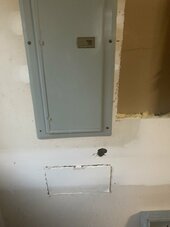
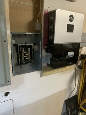
I have an EG4 6000XP mounted on the wall of my garage about 3 feet from my breaker panel. I need to run 4 wires L1 L2 neutral and ground out of the panel to the inverter which is on the wall. The wire will exit the panel inside of flexible nylon conduit.
I’m having a hard time coming up with a clean way of bringing the wires out of the drywall to the inverter.
There is an existing hole in the wall below the panel I’d like to use if possible.
Any ideas? Pictures?
I’m attaching a picture of my wall with the breaker panel and my sub panel and inverter.