diy solar

diy solar

Few questions to those that made DIY batteries.

I bought the 2-pole momentary switch online, - just a rocker switch with a spring inside so it is only "on" while I am pushing on the button.
Wire the pos and neg from main bus to the inverter input DC buses around your main disconnect for the ESS, and put a resistor on the Pos lead.

Here is a pic of a similar set up on my mobile DIY 8s pack. The main 2P Pack breaker in the photo is "ON". To precharge this breaker will be "OFF", then press and hold the precharge to charge up the inverter capacitors, then switch the breaker to "ON" with your other hand, and then let go of the pre-charge switch.

Electrically, the Line side neg is wired to the Main battery Neg, and the Load side Neg is wired to the pack terminal Neg. the Line side Pos is wired to the BMS output Pos, and the Load side Pos is connected to a small resistor (ebay/amazon/aliexpress) then to the pack terminal Pos.

{ As an added bit of protection I put an online automotive 10A fuse wired between the resistor and the pack terminal Pos - just to protect the small wire since otherwise the only protection is the BMS which on this pack is 150A which is too high for the small pre-charge wire ga.}
View attachment 209123
Thank you for this. Way more elaborate than I pictured. I thought it was something like a jumper with alligator clips on each end.
 
I "try" to keep alligator clips for temporary stuff/testing.
The parts are all cheap and it will take you less than an hour to set it up once, and then enjoy the convenience forever.
 
Two questions, Is this precharge resistor something that can be used temporarily, while commissioning or does it typically stay in the circuit? I'm picturing pre connecting with alligator clips and removing it once tph battery connection is made.
Second, Can you post a link to where I may purchase one?
TIA
Here's the resistor I use. YiePhiot 2PCS 50W 25 Ohm Resistor Aluminum Case Wirewound Chassis Mounted Compatible with Ring Doorbell, Nest Hello Doorbell, SkyBell Doorbell Etc https://a.co/d/7QaQHu6

I ran a wire lead to one end and jump the breaker for 5-10 seconds before closing it.
 
Two questions, Is this precharge resistor something that can be used temporarily, while commissioning or does it typically stay in the circuit? I'm picturing pre connecting with alligator clips and removing it once tph battery connection is made.
Second, Can you post a link to where I may purchase one?
TIA
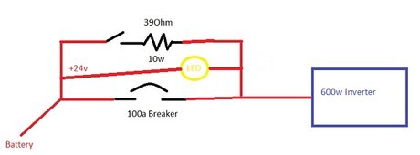
I built mine with a small project box, a momentary contact button, a LED, and a resistor to go around the main breaker. Since my systems are only used occasionally I tend to shut everything down so the pre charge resistor is Step 1 in my startup instructions. I have a small wire connected to each leg of the main DC breaker so the power goes in from the battery, around the main breaker, and out to the inverter.

Here's a wiring diagram of what I build with example numbers:

Precharge success.jpg
 
I built mine with a small project box, a momentary contact button, a LED, and a resistor to go around the main breaker. Since my systems are only used occasionally I tend to shut everything down so the pre charge resistor is Step 1 in my startup instructions. I have a small wire connected to each leg of the main DC breaker so the power goes in from the battery, around the main breaker, and out to the inverter.

Here's a wiring diagram of what I build with example numbers:

View attachment 209143
Exactly what I'm thinking of. Thanks.
 
So, for those interested, after an almost full charge at 0.3C my cells did increase the pressure on the fixture quite a bit. How do I know? I can see the 3mm mild steel sheet flexing under load.

It flexed so a gap of about 1mm appeared between the cell wall and the middle of the plate. But the cell has not swelled to fill the gap. This means I'll need to weld on a piece of support onto that sheet steel piece.

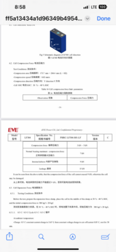
Also, I was incorrect that Higee doesn't mention compression in their datasheet. They don't mention it anywhere in the wording. But on the technical drawings of the cell where dimeeare given it says 71.8mm at 300kgf. So clearly they want 300kg of force on the cells too.

Edit: Now the task is to discharge them... Not so easy with 14kWh of energy.

BTW, how do you like my temporary "don't drop a washer" brand bus bars?

20240414_104155.jpg
 
Last edited:
What’s the clearance of those bus bars, 1/4”? That’s sketchy as shit right there.

Such an odd arrangement.

Also if the plate is bowing that means crazy about of pressure on the corners of the end cells, bad mojo can happen.
 
That arrangement would reduce the stress on bus bars from cell expansion, but that clearance would worry me. One solution would be narrower but thicker bus bars but that creates a challenge of getting them flat on the terminal tops.
 
What’s the clearance of those bus bars, 1/4”? That’s sketchy as shit right there.
Yes, that's about right. This is the only aluminium profile I could get with suffiecient area to complete this task on the weekend. It was only temporary and has been disassembled after I discharded the battery again. Essentially I wanted to:
- charge it with a 48V inverter close to full (I did, I stopped when one of the cells reached 3.51.)
- then I set up bus bars for parallell and I topped it up all the way (to 3.59 to be exact - which still took ~4h with 30A)
- then I left it for 4h
- finally I set it up as you can see on the picture and I discharged it down to 3.2V by running a 2kW heater for 7h+ (final SOC about 10% judging by the amount of energy used - it was showing 3.14V under load, but recovered to 3.2V which was my goal to avoid any swelling when I remove the compression fixture)
- then I removed the busbars and I disassembled the battery.
Such an odd arrangement.

Also if the plate is bowing that means crazy about of pressure on the corners of the end cells, bad mojo can happen.
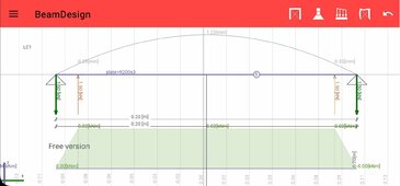
This is only 3mm mild steel plate and ~204mm (8in) between bolts. It doesn't take "a crazy amount of pressure" to bow the middle out by about a mm, maybe 1.5mm tops.

In fact I was curious how much force does it take. I have an app on my phone called beam design (for when I DIY various metal things) and according to it this amount of bow is pretty much 300kg. So it seems I've hit the mark without even knowing :-D

Screenshot_20240415_084207_BeamDesign.jpg

But seriously, I was concerned about all of that force beeing concentrated on the edges too. No doubt the insulation sheet protected it as after I removed the fixture I can't see any damage to the casing. Not even an imprint in plastic. For the permanent version I'll weld supports onto this plate so there is no flex and I've ordered disc washers for the bolts. The fact this plate flexed is probably good as it avoided applying too much force.

After some thinking I decided the battery doesn't really need insulation as it will be in a basement where I never had the temperature go below zero (it's around 5C all year), but I'll add heaters just in case.

That arrangement would reduce the stress on bus bars from cell expansion, but that clearance would worry me. One solution would be narrower but thicker bus bars but that creates a challenge of getting them flat on the terminal tops.

It definitely would be my preference, but all I could get without ordering in advance was 20,30,40 mm in 2mm thickness (under 1/8in thickness, about 3/4'',1in,1.5in) then there was this 50x3mm (2in x 1/8) bar that would leave me ~6mm clearance (1/4) so not much if a washer is dropped. But I was extra careful and it is dismantled by now.

I can do sketchy for a short time and not regret it... I'd not leave it like this.

Edit: I have an extra bit of info someone might find interesting:
Initially (after the battery was charged, but before bus bars were removed) the plate flex was almost inperceptible. I mean I looked at it and I wondered, is this plate flexing? It looks like it does a bit, but I'm not sure. I wish I used feeler gauge to measure, but I didn't. It certainly was a tiny flex. Then I removed the busbars to do the parallell arangement and only then the plate flexed by 1mm (maybe up to 1.5mm as said before, but most likely between 1 and 1.5). This means that just the busbars with screws torqued with a torque wrench to 6Nm were holding the batteries.

This makes me think, if you put your busbars on when batteries are discharged, torque them, then charge, you may actuallybe applying "compression" to all but the end cells without even knowing.

Also, the batteries did shrunk again, after I discharged them back to (recovered) 3.2V. I believe it is not ideal to store them too long at such low SOC (10%) but I wanted to ensure they go back to the same size and it is hopefully only for a week or two at most.
 
Last edited:
Yes, that's about right. This is the only aluminium profile I could get with suffiecient area to complete this task on the weekend. It was only temporary and has been disassembled after I discharded the battery again. Essentially I wanted to:
- charge it with a 48V inverter close to full (I did, I stopped when one of the cells reached 3.51.)
- then I set up bus bars for parallell and I topped it up all the way (to 3.59 to be exact - which still took ~4h with 30A)
- then I left it for 4h
- finally I set it up as you can see on the picture and I discharged it down to 3.2V by running a 2kW heater for 7h+ (final SOC about 10% judging by the amount of energy used - it was showing 3.14V under load, but recovered to 3.2V which was my goal to avoid any swelling when I remove the compression fixture)
- then I removed the busbars and I disassembled the battery.

This is only 3mm mild steel plate and ~204mm (8in) between bolts. It doesn't take "a crazy amount of pressure" to bow the middle out by about a mm, maybe 1.5mm tops.

In fact I was curious how much force does it take. I have an app on my phone called beam design (for when I DIY various metal things) and according to it this amount of bow is pretty much 300kg. So it seems I've hit the mark without even knowing :-D

View attachment 209405

But seriously, I was concerned about all of that force beeing concentrated on the edges too. No doubt the insulation sheet protected it as after I removed the fixture I can't see any damage to the casing. Not even an imprint in plastic. For the permanent version I'll weld supports onto this plate so there is no flex and I've ordered disc washers for the bolts. The fact this plate flexed is probably good as it avoided applying too much force.

After some thinking I decided the battery doesn't really need insulation as it will be in a basement where I never had the temperature go below zero (it's around 5C all year), but I'll add heaters just in case.


It definitely would be my preference, but all I could get without ordering in advance was 20,30,40 mm in 2mm thickness (under 1/8in thickness, about 3/4'',1in,1.5in) then there was this 50x3mm (2in x 1/8) bar that would leave me ~6mm clearance (1/4) so not much if a washer is dropped. But I was extra careful and it is dismantled by now.

I can do sketchy for a short time and not regret it... I'd not leave it like this.

Edit: I have an extra bit of info someone might find interesting:
Initially (after the battery was charged, but before bus bars were removed) the plate flex was almost inperceptible. I mean I looked at it and I wondered, is this plate flexing? It looks like it does a bit, but I'm not sure. I wish I used feeler gauge to measure, but I didn't. It certainly was a tiny flex. Then I removed the busbars to do the parallell arangement and only then the plate flexed by 1mm (maybe up to 1.5mm as said before, but most likely between 1 and 1.5). This means that just the busbars with screws torqued with a torque wrench to 6Nm were holding the batteries.

This makes me think, if you put your busbars on when batteries are discharged, torque them, then charge, you may actuallybe applying "compression" to all but the end cells without even knowing.

Also, the batteries did shrunk again, after I discharged them back to (recovered) 3.2V. I believe it is not ideal to store them too long at such low SOC (10%) but I wanted to ensure they go back to the same size and it is hopefully only for a week or two at most.
Cool little app for the bending beam force calculator.

Glad to know it was just temporary. Knowing the surface area of the edges is so small nothing good could have come keeping that much pressure on such a small area compared to the rest of the cells.

When you did charge the full 48v assembled battery bank until a cell bit 3.51v how big a delta was there in cell voltages?

Was the delta <0.010v?
 
Cool little app for the bending beam force calculator.

Glad to know it was just temporary. Knowing the surface area of the edges is so small nothing good could have come keeping that much pressure on such a small area compared to the rest of the cells.
I'll definitely prevent this for the next use of the fixture.
When you did charge the full 48v assembled battery bank until a cell bit 3.51v how big a delta was there in cell voltages?

Was the delta <0.010v?
No it was higher, no doubt due to my previous un-equalisation effort. During the most of the string charge it fluctuated around 20~60mV as the BMS was actively balancing. The balance current was pegged at 2A/-2A and the high and low cells would change frequently, but I got an impression the first and the last in the string were higher more often.

At the very end of the charge if I remember correctly the highest was 3.51V but the lowest was 3.43 so a substantial difference of 80mV. They were in two groups of 8 (I did try charging them in groups of 8 before). The first group was lower and the second group was higher. Within the group they were within about 10mV. I decided I'd rather have to equalise longer when in parallel than risk overvolting and resulting bms cut off.

Only after I additionally topped it up with almost 300Ah connected in parallel they equalised fully. From then on the difference was much better. After equalisation batteries were all within 1mV.

Then when I started discharging it was around 5~15mV during the discharge. When I stopped the discharge and left them to settle they equalised to few mV again.
 
How do you know you aren’t over compressing the cells?

View attachment 209440
I personally used a scale to judge the force on the screws, then repeated that amount of torque.

I'm practice you want tight (you can't move cells in the middle) but not crushing.

I have 24 long strings compressed like this, there is no cell movement from empty to full.

In practice when you actually have the bolts and threaded rods attached you can tell the different.

The actual window of acceptable pressure is pretty high as long as you don't crush them. If they are tight enough that you can't move the cells then you've done plenty imo and have truly fixed them in place.
 
Reading some of the above, people like to play with their cells and go through a lot of effort.

At a minimum all you need to do is:

Get some shelving, probably wooden
Take the cells out of the shipping boxes and put the cells on the shelves positive to negative.
Attach cell compression using steel rods (maybe 1/4 inch, I forget exactly)
Attach bus bars
Attach BMS
Attach active balancer (you can get really high amp ones now like the nee)
Attach to the inverter
Turn on and use system

Double-check everything, check resistance of all connections, functionality of BMS/ balancer. Voltage settings etc.

Good to go.

Nothing else is really required.

Two strings in parallel is safe without issues. Three is pushing it. With more you need fuses in case of failure. I suggest doing the cells in parallel, then you can save money on the BMS and balancers.

Once you are setup you should never need to check or monitor anything on the system. People LOVE their monitoring software, but that's all hobby talk. Make everything automatic do you doing think about it for months. All you should be getting is an alert to change the oil on your generator.
 
Last edited:
Reading some of the above, people like to play with their cells and go through a lot of effort.

At a minimum all you need to do is:

Get some shelving, probably wooden
Take the cells out of the shipping boxes and put the cells on the shelves positive to negative.
Attach cell compression using steel rods (maybe 1/4 inch, I forget exactly)
Attach bus bars
Attach BMS
Attach active balancer (you can get really high amp ones now like the nee)
Attach to the inverter
Turn on and use system

Double-check everything, check resistance of all connections, functionality of BMS/ balancer. Voltage settings etc.

Good to go.

Nothing else is really required.

Two strings in parallel is safe without issues. Three is pushing it. With more you need fuses in case of failure. I suggest doing the cells in parallel, then you can save money on the BMS and balancers.
If you don’t want to go by manufacturer specifications. What else should we short cut on?
 
How do you know you aren’t over compressing the cells?
IMO the easiest way is disc springs and threadlocker. There are online calculators you can put your disc spring dimensions in and how much you compress it. This gives you the force. For example I know when my disc springs arrive (1in diameter, 0.5in bore, 0.05in thick) I need to compress 20%. Then you threadlock so the nuts don't back out.

BTW, my cells are Higee, you had Eve's datasheet there :)

Reading some of the above, people like to play with their cells and go through a lot of effort.
Indeed, it's a hobby for many people. However, although it is my hobby I'm trying to meet the manufacturers spec so I can reliably tell 5/10 years down the line "have these been good cells"? Also if they fail there is no excuse that it is my fault.

But yes, you're kind of right too. There is a very good argument made by the guy from the "Off grid garage" that you'd have cycle the cells daily hard(like in a car) to notice a difference from compression before the cells deteriorate with time. Especially for him, living in a hot climate this makes sense.

But not everyone lives in a hot climate. Also, the calendar life of the latest lifepo4 is very much an estimate. It hasn't been in the market long enough to tell what happens 10 years down the line. Before anyone says we had lfp 10 years ago let me say manufacturer's upgrade their chemistry on an almost yearly basis. Look at the recent "tesla battery deterioration data" on YouTube and you'll see how every 2 years there is a different battery.

Finally, you never know what live brings. You may say, who cares in 7 years down the line these cells drop in capacity rapidly and had I compressed them they'd last 10. There will be better chemistries I'll most likely want to replace them well before then. But you don't know, what if you have no money, or time to deal with it then?

So that's why I decided to compress my cells :)
 

diy solar

diy solar
Back
Top