diy solar

diy solar

Need to buy/make thicker gauge wires for outside, but problem

whereitsat42

New Member
Joined
Nov 13, 2023
Messages
20
Location
Central Jersey
Hi all, need some help: my panels are installed on ground mounts between 45-65 feet from my junction box and, like a moron, I made the classic mistake of not doubling the length of my cable runs from the panels to the box when sizing my wires, and need to upgrade from the 10 awg wires I have now. I have four inputs on my junction box, each connected to three 320w/24v panels in series (so roughly 13.3 amps/72v max apiece), and according to my consultation of THE CHART, and accepting a moderate but not horrible voltage drop, 6 awg seems to be the way to go. Only problem is I can't seem to find 50-65 foot 6 awg cables anywhere with the mc4 connectors already on them. I can get just the copper wire, but can't find 6 awg connectors for sale either. I'm assuming the 45-65 feet, while not ideal, also isn't radically uncommon, so does anyone know somewhere reliable where I could find this stuff reasonably easy? As an added bonus, have I already fried anything running 10 awg cables, or has the charge just dropped off to practically nothing using that wire?
 
Can't say this is to code, but I would put this on a busbar with the 10 AWG on one side and 6 AWG on the other in an enclosed container.

What I have done to to make a 10 AWG --> 6 AWG connection for a 900 watt panel run, is fold the 10 AWG over and insert it to a 6 AWG butt crimp, and put the 6 AWG on the other side and then crimp them and put two pieces of glue heat shrink over this. I use this as an extension cable for a array of portable panel for my RV. Definitely not to code.

If you could increase the voltage by going 6S 2P, this should keep so you could use 10 AWG, but might not be friendly with the 10 AWG.
I appreciate the suggestion but do kind of want to keep this to code, especially where all this is located on my property: it's right up by the property line and the neighbor on the other side already started asking some questions, so I don't want to give him any more to make an issue out of than necessary.
 
Hi all, need some help: my panels are installed on ground mounts between 45-65 feet from my junction box and, like a moron, I made the classic mistake of not doubling the length of my cable runs from the panels to the box when sizing my wires, and need to upgrade from the 10 awg wires I have now. I have four inputs on my junction box, each connected to three 320w/24v panels in series (so roughly 13.3 amps/72v max apiece), and according to my consultation of THE CHART, and accepting a moderate but not horrible voltage drop, 6 awg seems to be the way to go. Only problem is I can't seem to find 50-65 foot 6 awg cables anywhere with the mc4 connectors already on them. I can get just the copper wire, but can't find 6 awg connectors for sale either. I'm assuming the 45-65 feet, while not ideal, also isn't radically uncommon, so does anyone know somewhere reliable where I could find this stuff reasonably easy? As an added bonus, have I already fried anything running 10 awg cables, or has the charge just dropped off to practically nothing using that wire?
I would just use 6/2 UF wire for that run, available anywhere.

Edit: If the 4 strings are making the 65ft run each on their own, they are fine at 10awg.

Having 3 strings already requires fusing each string so a combiner box makes sense to make the transition. No need for MC4 connectors.

 
Last edited:
Where is your charge controller or inverter? Is it on the other end of this wire from the array?

You do not have to size the PV circuit for voltage drop. It only needs to hold the amps. If it's a 20 amp array, then 10 awg can carry it unlimited distance. All you lose from the distance is some watts.
 
I appreciate the suggestion but do kind of want to keep this to code, especially where all this is located on my property: it's right up by the property line and the neighbor on the other side already started asking some questions, so I don't want to give him any more to make an issue out of than necessary.
Silence is golden… be careful of neighbors …unless he has got money in your system he probably cannot be trusted to not talk about stuff.
 
Hi all, need some help: my panels are installed on ground mounts between 45-65 feet from my junction box and, like a moron, I made the classic mistake of not doubling the length of my cable runs from the panels to the box when sizing my wires, and need to upgrade from the 10 awg wires I have now. I have four inputs on my junction box, each connected to three 320w/24v panels in series (so roughly 13.3 amps/72v max apiece), and according to my consultation of THE CHART, and accepting a moderate but not horrible voltage drop, 6 awg seems to be the way to go. Only problem is I can't seem to find 50-65 foot 6 awg cables anywhere with the mc4 connectors already on them. I can get just the copper wire, but can't find 6 awg connectors for sale either. I'm assuming the 45-65 feet, while not ideal, also isn't radically uncommon, so does anyone know somewhere reliable where I could find this stuff reasonably easy? As an added bonus, have I already fried anything running 10 awg cables, or has the charge just dropped off to practically nothing using that wire?
The more i think about this. Thats a fairly low VOC. what do you have for a charge controller?

Raise the voltage on your strings and lower the current. Then you can keep the 10awg. Maybe a new charge controller with higher voc is appropriate. Alot less work and maybe a wash on costs.

Edit: If you ran each string separately the 65ft run, no change required. I was assuming they were combined first.
 
Last edited:
  • Like
Reactions: JRH
The more i think about this. Thats a fairly low VOC. what do you have for a charge controller?

Raise the voltage on your strings and lower the current. Then you can keep the 10awg. Maybe a new charge controller with higher voc is appropriate. Alot less work and maybe a wash on costs.
So my panels are 320 watt/24 volt panels, and I divided watts by volts to get 13.3333 amps per panel. I have three of these panels in series per string, so 24x3=72 volts, ergo 13.3 amps/72 watts per string. I have a 100 amp Epever MPPT charge controller. I'm not sure how I would lower the current, I thought the way the math worked when wiring in series is the current (the 13.333 amps) stays the same, and I add the voltage of all the connected panels, getting me to 72. I know wiring in parallel INCREASES the current, but I'm not aware of any way to reduce it without introducing resistance to intentionally decrease the efficiency of my setup. Is that wrong?

Also, I have MC4 connectors on both the junction box and the panels, and I have no idea how to weld nor the inclination to learn just for this, I would really prefer something I can just plug in and it will work.
Where is your charge controller or inverter? Is it on the other end of this wire from the array?

You do not have to size the PV circuit for voltage drop. It only needs to hold the amps. If it's a 20 amp array, then 10 awg can carry it unlimited distance. All you lose from the distance is some watts.
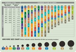
Each string connects to the junction box outside the house, junction box connects to charge controller inside the house via a roughly 10 foot, 6 awg wire. The unlimited distance you mention flies in the face of everything I've ever read that you need thicker cable to carry the same current over longer distances. I thought that was the entire point of this chart. 13.3 amps per string, so call it 15 amps with the furthest string being 65 feet from the junction box, so 130 feet per string because the circuit length includes one physical wire in each direction. No?
chart.jpg
 
I would just use 6/2 UF wire for that run, available anywhere.

Having 3 strings already requires fusing each string so a combiner box makes sense to make the transition. No need for MC4 connectors.

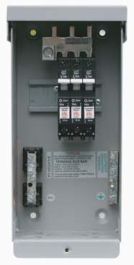
And when I say junction box, this combiner box is what I meant. There's a fuse on the connector going to each string, and a master fuse with an on/off switch on the connection going inside to the charge controller.
 
So my panels are 320 watt/24 volt panels, and I divided watts by volts to get 13.3333 amps per panel. I have three of these panels in series per string, so 24x3=72 volts, ergo 13.3 amps/72 watts per string. I have a 100 amp Epever MPPT charge controller. I'm not sure how I would lower the current, I thought the way the math worked when wiring in series is the current (the 13.333 amps) stays the same, and I add the voltage of all the connected panels, getting me to 72. I know wiring in parallel INCREASES the current, but I'm not aware of any way to reduce it without introducing resistance to intentionally decrease the efficiency of my setup. Is that wrong?
What is the exact VOC of the panels? should be on the label. We need this before moving forward. What is your battery voltage?

If your charge controller has the room (i beleive yours is 150voc max), you could for instance Reconfigure to 4S3P. This raises the voltage and eliminates an entire string of 13amps. Same wattage goes to charge controller in the end. Even 6S2P but we need rated VOC before figuring this.

Did you do any harm, doubt it. Too small of wire will just get hot. Will it carry 60A?, yes for a little while, but it will get hot eventually in continuous duty. Your components wont know the difference until you get large enough voltage drop to effect function.

This is the benefit to high VOC charge controllers is less strings, smaller wire, higher voltage, more efficient for longer runs.
 
The unlimited distance you mention flies in the face of everything I've ever read that you need thicker cable to carry the same current over longer distances. I thought that was the entire point of this chart.
PV circuits have many unique qualities to them. In a nominal voltage supply system you want or need to keep the voltage from dropping too low for the devices. Utility gives you 120, you want 120ish at the load device, battery gives you 12v, you want 12vish at the load device. PV gives you 72 volts, it's not a problem if you only get 65v at the charger, or less.
 
What is the exact VOC of the panels? should be on the label. We need this before moving forward. What is your battery voltage?

If your charge controller has the room (i beleive yours is 150voc max), you could for instance Reconfigure to 4S3P. This raises the voltage and eliminates an entire string of 13amps. Same wattage goes to charge controller in the end. Even 6S2P but we need rated VOC before figuring this.

Did you do any harm, doubt it. Too small of wire will just get hot. Will it carry 60A?, yes for a little while, but it will get hot eventually in continuous duty. Your components wont know the difference until you get large enough voltage drop to effect function.

This is the benefit to high VOC charge controllers is less strings, smaller wire, higher voltage, more efficient for longer runs.
Panel VOC is 40.30 V. (Not sure if you saw the other comment but I edited when I realized you meant reconfiguring the panels and not the batteries).
 
Panel VOC is 40.30 V. (Not sure if you saw the other comment but I edited when I realized you meant reconfiguring the panels and not the batteries).
Ok then you cant really go more than 3 series without a new CC, we can scratch that idea. Your string voltage is 120.9 for charge controller sake.

Rated voltage Vmpp (also on lable) would be what the voltage will drop to while charging.

Rated current Impp would be max current used when calculating your wire size. I have a feeling this is less than 10A
You are correct, it is just under 10A, which means that, according to that chart up there, I can get away with 8 awg for a 130 ft round trip, and don't need to worry abut 6 awg, does that sound right to you?
 
You are correct, it is just under 10A, which means that, according to that chart up there, I can get away with 8 awg for a 130 ft round trip, and don't need to worry abut 6 awg, does that sound right to you?
Yes

Edit: 10awg is fine for 10A. If they were combined prior to making the 65ft run, 8awg would be required.
 
Last edited:
Sizing wire runs for me is a two step process.

1. First meet code. Isc x 1.25 (it used to be Isc x 1.56)

2. Then look at voltage drop keeping in mind that your array will spend almost all of its life at 80% of Imp. Rarely, if ever, will you need to up size the wire from step one.
 
So you have 4 strings of 3 panels at like 72v 14A each string. They all travel 65 feet separately, on a total of 8x 10awg conductors, where they combine onto 6 awg wire and each string is fused at the combiner at 15 or 20A. Is that all correct?

That would all be fine, only a 100 watts lost to voltage drop at full rated output. It's more than adequate it's already overbuilt and does not need to be changed.
 
Back
Top