Joe Samra
Medical Electronics Engineer
- Joined
- Apr 21, 2022
- Messages
- 13
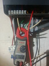
Tim is using an AC/DC clamp ammeter (hall effect), can read DC current.
Joe has an AC only clamp ammeter (current transformer)
Possibly, "No batteries" has something to do with undesired behavior. Can you connect a batch of car batteries?
Then observe any difference in AC current, and read battery current with the AC scale you have (reads AC ripple but not DC.)
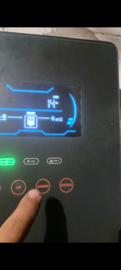
Tim - besides AC current in AC grid connection as requested, check AC current in battery cable (with and without grid connected).
I would expect that to be low under no load, but who knows. Likely has ripple when charging.
I find that when driving a large AC load from batteries, although battery DC (average) current matches load wattage, there is a large AC ripple. Capacitors can't buffer 60 Hz, only the higher frequencies of switcher. At least with my low-frequency inverter.
Joe - does your friend also have batteryless setup?
Without AC input, just PV, at least average current has to come from PV panels. Possibly peak current at top of sine wave. But I would guess a high frequency inverter would draw down capacitors to deliver peak current, at least in the batteryless case.
But I still don't know where 2A would be going. That's too much current draw on AC input when there isn't that much current on AC output.
This one?
Customized Solar Power System,Growatt Hybrid System,Split Phase PV System - Swtsolarpv.com
China supplier of solar system - off grid solar system,lithium battery storage system,solar power station offered by Sweet Power. Any questions,pls do not hesitate to contact us!www.swtsolarpv.com
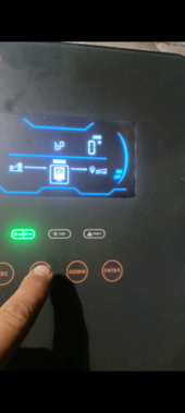
"PV & Grid Power combine if PV energy is insufficient for load."
"
"
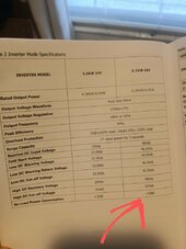
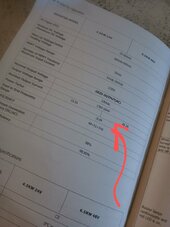
AC CHARGER AC Charge Current 80A AC Input Voltage 230VAC Frequency Range 50/60HZ
A simple UPS function can be implemented with a relay - either pass grid through to load, or disconnect from grid and use inverter.
Much more difficult is to combine PV and Grid on AC side, requires synchronized AC waveform and protection against backfeed to grid. Grid-tie hybrid inverters to this.
To accomplish the function more simply, a separate battery charger can be used, an "on-line UPS" or "double-conversion". AC is converted to DC, then DC to AC.
That still shouldn't explain 460W consumption, but possibly the battery charger is using significant inductance of a transformer to block AC current. 80A at 50V = 4000W. 2A at 230V = 460W, 11% of full-load current.
No-load current of a transformer is a thing. Some references say should be under 5%.
Probably more cheaply built and undersized will allow more.
I'm presently delving into transformer core characteristics, and there is a LOT of science and engineering detail in there. After metal is worked into the shape desired, it has to be annealed to restore desirable characteristics. This can be done without magnetic field, or with field in longitudinal or transverse direction. Those produce considerable differences in behavior, good for various applications. Power transformers are just one of many.
Likely, most of that 2A and 460VA is reactive power, not real power. But if your utility meter doesn't distinguish, that doesn't do you any good. (It also means you wouldn't be able to spin the meter backwards like we do with grid interactive inverters for net metering.)
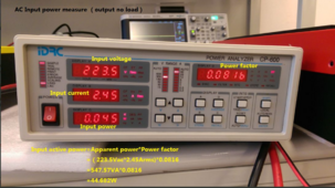
I ran a test of a transformer type battery charger.
On 10A (12V) setting, it draws 0.00A at 120Vrms.
On 55A (12V) "start" setting, it hums moderately loudly and draws 1.18A at 120 Vrms.
That's zero W delivered on 660W setting, 142VA reactive power drawn, 21% of full-load current.
I suspect the GroWatt has a cheap undersized transformer for the battery charger (not a high frequency switcher, and not a larger heavier transformer.) At 50 Hz vs. 60 Hz the transformer goes further into saturation, also at 240V vs. 220V.
View attachment 92402 View attachment 92403
If this is what's going on, maybe best to resell it to someone who would only use it for solar, or downstream of their generator. They can run the generator briefly for larger loads, then turn off and run smaller loads from battery.
Alternatively, disconnect from grid, and get a different battery charger without such no-load draw. But it must properly regulate for the batteries you're using, either regulated voltage or have a "maintain" function that is OK to leave plugged in continuously.
Hello Hedges, my friend has 4 Amaron batteries installed in his system, he conducted the test i required with batteries breaker turned off and AC output breaker too.
I installed in my panel a modular AC contactor to pass through AC grid to my house without passing by the inverter, i guess it is a normal behavior for growatt to withdraw 2 amps from grid without batteries since @timselectric , me and my friend had the same results, im going to wait for my batteries to arrive, until then i only use the inverter for small loads when needed (not the refrigerator because upon starting its surge is way strong for 4 x 655W panels to handle so the inverter trips and indicates PV power insufficient).
Thank you so much for your help, i really appreciate it.
")