diy solar

diy solar

Option to bypass inverter - Transfer switch?

Those terminal blocks are meant for low voltage, not exposed hazardous voltages.
You can find set-screw types that accept your wire gauge, and have a cover.

US code says not to put two wires into one terminal that isn't rated for it.
I'd be tempted to strip 1" of insulation off the middle of a wire, fold it in half, twist, and insert in Breaker (RCD) terminals.
Viola! A "V" (use similar to "Y") connection.

I also use multi-port set-screw connectors (Polaris), or split-bolts wrapped in rubber tape then vinyl tape.
 
I'd be tempted to strip 1" of insulation off the middle of a wire, fold it in half, twist, and insert in Breaker (RCD) terminals.
Ok that is next-level genius. Great idea.
 
Does something like an RCD have defined "input" and "outputs" or either set of terminals can be used as the input or output?
 
Those terminal blocks are meant for low voltage, not exposed hazardous voltages.
You can find set-screw types that accept your wire gauge, and have a cover.

US code says not to put two wires into one terminal that isn't rated for it.
I'd be tempted to strip 1" of insulation off the middle of a wire, fold it in half, twist, and insert in Breaker (RCD) terminals.
Viola! A "V" (use similar to "Y") connection.

I also use multi-port set-screw connectors (Polaris), or split-bolts wrapped in rubber tape then vinyl tape.
According to my local regulations, we are allowed to put two wires in the same terminal, as long as they are the same guage.

If you do go this way, make sure to tighten well, and then pull on each wire separately, to make sure it has a good connection.

But this two wires don't necessarily need to go to your loads panel, you could just jumper the outputs, Neutral to Neutral, Line to Line, etc. That way you have less wires to run to your panel (only 1 set).

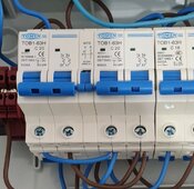
Look at how my outputs (bottom of the transfer switch) are wired:
SmartSelect_20240516-051255_Gallery.jpg
 
Does something like an RCD have defined "input" and "outputs" or either set of terminals can be used as the input or output?
Depends on your specific equipment. Some RCDs have "Line" and "Load" or "Input" and "Output" markings.
If your specific RCD doesn't have such markings, I guess it matters less.
 
you could just jumper the outputs, Neutral to Neutral, Line to Line, etc. That way you have less wires to run to your panel (only 1 set).
I like that option. Thanks for that idea! Picture was helpful too.
 
Is there any reason I can't use the RCD I purchased as the on/off breaker for the inverter input?
It looks like it would function fine for that purpose.
On my main panel it has a 60A breaker before the RCD, which makes me wonder if a breaker should come first.
 
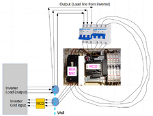
@timselectric @Hedges @meetyg For the sake of any noobs like me who might need to wire a similar circuit, here's my bypass wiring diagram. I need an RCD because that's how it's done in Japan. Any critiques or suggestions for improvements would be appreciated!

final-wiring-transfer-v2.png
 
here is a great little video on powering a home with grid or off grid operation without a full blown transfer switch. I came across this video a month or so ago

it's pattern can be replicated with smaller scale equipment, if line side TAPs are allowed


also note the following comment. due to this comment I found a code violation in my system and refactored it,
I now send grid power to my inverter THROUGH my transfer switch and then inverter power BACK to the transfer switch, keeping the 2 ungrounded conductors and SINGLE neutral conductor in the same conduit. before I had separate conduits for the same neutral

@maths9085

3 months ago

@jmuller86 Nice upgrade to the wiring configuration. Putting your new disconnect above the main panel sideway would be fine, no prohibition on that in the NEC. But I see that you have two neutral conductors terminated on the EG4 neutral busbar. Both of those originate from your main panel, one going through the new 70A disconnect above and then down the new LFMC to the inverter, the other going down through the LFMC that goes out the bottom of the main panel to the inverter. If you think about it, those two conductors are in parallel: they both originate at the same busbar (main panel) and ultimately terminate at the same busbar (inverter). Which means that constitutes a 310.10(H) violation, as they are smaller than 1/0.Perhaps more importantly, any neutral current between the inverter and the main panel will divide along the two paths, regardless of the state of your interlocked breakers. So you'll have a 300.3(B) violation, as not all the conductors of the circuit are in the same conduit. The solution to both problems is to use only one neutral conductor between the main panel busbar and the inverter busbar, and to route it along with both your (2) interlocked 70A breaker ungrounded conductors and your (2) new 70A tap conductors in a single conduit run that has all 5 conductors. You can use either the upper route through the new 70A disconnect, or the lower route through the bottom of your main panel. If you use the lower route, then you could also delete the neutral wire that goes from the main panel to your new 70A disconnect. Plus the lower route is shorter, so it looks like you'd be under 24" and not have to worry about derating for 4 CCCs.
 
Last edited:
I saw that video ealier. It is a good solution to the problem that that SolArk 15k and the EG4 do not have an AC input breaker. It does not eliminate the automatic transfer swith in those inverters, but eliminates the need for a manual transfer switch used for maintenance.
 
Any critiques or suggestions for improvements would be appreciated!
What prevents you from turning on both breaker sets and crossing grid to load?

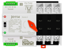
Why not use one of these:

1717381716638.png


Assures no crossing, can be switch manually, and it can switch automatically if inverter load fails.

This isn't a breaker, however, so a breaker set may be required on the inverter output.

I'm sad I can't use something like that in the USA since it doesn't meet standards here.

Mike C.
 
Last edited:

diy solar

diy solar
Back
Top