offgrid-curious
Solar Enthusiast
I recently “finished” the upgrade to my off grid cottage solar system (are we ever really done?). The previous system was 12V with 2 panels (250W? I can’t remember), 4 6V FLA batteries (2S2P) and a small 400W inverter. Most of the larger appliances (stove, water heater, fridge) and some lights were powered by propane.
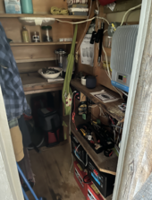
I wanted to upgrade the system so that we could have reliable Internet with Starlink as well as add more modern conveniences like a microwave, toaster oven, coffee maker, TV, etc. There are some challenges with my location. It’s heavily treed and I didn’t want to cut any trees down for PV. The roof is east-west and not ideal. And the cottage itself is 3 season. There is also a limited amount of space to put equipment because the cottage is relatively small. The existing system was in a small closet:
I ended up going with a Victron system mainly because of their solid reputation and reliability and low idle power consumption. I also like the modularity, in that I can select specifically what components I need, that work best for me. The monitoring with VRM was also appealing, as I’m nearly 2 hours away from the system. One of my goals was to spend the time to build a system, but not have to spend a lot of time maintaining it (unless I want to, that is).
I roof mounted 6 panels (Longi LR4-60HPB-350M) on each side of the roof in 3S2P. I hired a local company to do the panel install, which was very challenging, as it’s a steep corrugated metal roof (12:12 pitch). I used Kinetic Solar Rhino mounts to attach the rails to the roof. I added squirrel guard around the panels to hopefully prevent any critters from getting under there. The wiring was run from the roof in the soffits down to a MNPV6 combiner that I used as a junction box. I added MNSPD-300 surge protectors for each array. From the junction box, I used a 4 conductor 8 AWG Teck90 cable to run the PV into the cottage.
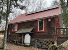
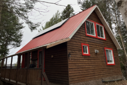
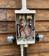
The previous system had no ground system. Because the soil is quite rocky, I opted to use a grounding plate instead of trying to drive a ground rod. I buried the plate 2’ deep and connected it with 6 AWG wire to the ground bus bar in the MNPV6.
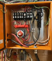
On the inside, the challenge I had was laying out all of the components so they would fit in the space I have available. I took all of the measurements of the closet and used SmartDraw to lay everything out. I used Panduit wire duct to route/hide wiring. It’s made out of PVC and is rated to 50C, but in my case, I don’t expect my wire temperatures to run anywhere close to that hot. I put all of my breakers and bus bars in a Vevor 20x20x6 enclosure. I used Midnite Solar breakers and Pike Industries bus bars. I used a Marinco 771-S-EZ switch to connect the battery. I modified the switch to add a pre-charge resistor circuit, which is active on the “1” position of the switch.
For the Victron components, I have:
Something I found incredibly helpful when assembling everything was using a YR1035+ internal resistance tester to check the resistance between all of my connections. This is to ensure that all of my crimps and various connections were tight and will perform well even under load.
I also added a Homeline subpanel for all of my AC loads.
I built a 304Ah DIY heated battery, which I’ll probably talk more about in another post.
Learnings and Conclusion
There are a few things that I may have done differently if I were to start again today. I think my initial energy budget was too conservative. For example, I budgeted 2.5kWh/day for Starlink and networking equipment. What I’m observing is less than half of that. I’m generating so much power that I sold the propane fridge and replaced it with a regular electric fridge.
Having never used solar before, I didn’t appreciate how much power is generated even in less than ideal conditions. With my 4.2kW array, I can still charge my battery usually before noon, even when it’s cloudy. When I originally built the system, I was thinking it could take days to recharge. My lowest battery SoC about 65%, and that was when I was running my absorption fridge off of electricity with 3 days of overcast. Part of this could just be the time of year, and I may be singing a different tune in December. But I probably could have gotten away with half the number of panels and a 100Ah battery and been just fine.
I learned a TON throughout this process and most of it was on this forum, so thanks to everyone for posting -- and reading!
I wanted to upgrade the system so that we could have reliable Internet with Starlink as well as add more modern conveniences like a microwave, toaster oven, coffee maker, TV, etc. There are some challenges with my location. It’s heavily treed and I didn’t want to cut any trees down for PV. The roof is east-west and not ideal. And the cottage itself is 3 season. There is also a limited amount of space to put equipment because the cottage is relatively small. The existing system was in a small closet:

I ended up going with a Victron system mainly because of their solid reputation and reliability and low idle power consumption. I also like the modularity, in that I can select specifically what components I need, that work best for me. The monitoring with VRM was also appealing, as I’m nearly 2 hours away from the system. One of my goals was to spend the time to build a system, but not have to spend a lot of time maintaining it (unless I want to, that is).
I roof mounted 6 panels (Longi LR4-60HPB-350M) on each side of the roof in 3S2P. I hired a local company to do the panel install, which was very challenging, as it’s a steep corrugated metal roof (12:12 pitch). I used Kinetic Solar Rhino mounts to attach the rails to the roof. I added squirrel guard around the panels to hopefully prevent any critters from getting under there. The wiring was run from the roof in the soffits down to a MNPV6 combiner that I used as a junction box. I added MNSPD-300 surge protectors for each array. From the junction box, I used a 4 conductor 8 AWG Teck90 cable to run the PV into the cottage.


The previous system had no ground system. Because the soil is quite rocky, I opted to use a grounding plate instead of trying to drive a ground rod. I buried the plate 2’ deep and connected it with 6 AWG wire to the ground bus bar in the MNPV6.
On the inside, the challenge I had was laying out all of the components so they would fit in the space I have available. I took all of the measurements of the closet and used SmartDraw to lay everything out. I used Panduit wire duct to route/hide wiring. It’s made out of PVC and is rated to 50C, but in my case, I don’t expect my wire temperatures to run anywhere close to that hot. I put all of my breakers and bus bars in a Vevor 20x20x6 enclosure. I used Midnite Solar breakers and Pike Industries bus bars. I used a Marinco 771-S-EZ switch to connect the battery. I modified the switch to add a pre-charge resistor circuit, which is active on the “1” position of the switch.

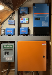
For the Victron components, I have:
- - Multiplus II 48/3000. (I regret not getting the 5000, even though I don’t need it — I had the space!)
- - Two SmartSolar MPPT 150/45s
- - Cerbo GX
- - Orion-Tr 48-12 — this powers all of the existing 12V system
- - 7” touch screen
Something I found incredibly helpful when assembling everything was using a YR1035+ internal resistance tester to check the resistance between all of my connections. This is to ensure that all of my crimps and various connections were tight and will perform well even under load.

I also added a Homeline subpanel for all of my AC loads.
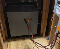
I built a 304Ah DIY heated battery, which I’ll probably talk more about in another post.

Learnings and Conclusion
There are a few things that I may have done differently if I were to start again today. I think my initial energy budget was too conservative. For example, I budgeted 2.5kWh/day for Starlink and networking equipment. What I’m observing is less than half of that. I’m generating so much power that I sold the propane fridge and replaced it with a regular electric fridge.
Having never used solar before, I didn’t appreciate how much power is generated even in less than ideal conditions. With my 4.2kW array, I can still charge my battery usually before noon, even when it’s cloudy. When I originally built the system, I was thinking it could take days to recharge. My lowest battery SoC about 65%, and that was when I was running my absorption fridge off of electricity with 3 days of overcast. Part of this could just be the time of year, and I may be singing a different tune in December. But I probably could have gotten away with half the number of panels and a 100Ah battery and been just fine.
I learned a TON throughout this process and most of it was on this forum, so thanks to everyone for posting -- and reading!


