diy solar

diy solar

Diagnosing sun gold power 6000 watt

joesmith123

New Member
Joined
Mar 1, 2023
Messages
419
Location
earth
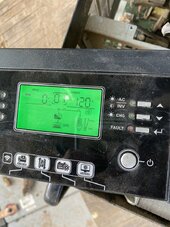
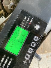
Error code 09

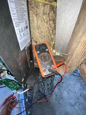
Details before it went out: It would lose connection to the 48 volt battery system, the display read 38 volts but when I check with volt meter, it says 48 volt

IMG_1200.jpeg

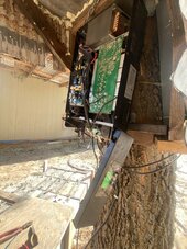
took off the cover, I do have multimeter, how do I check what is the problem?
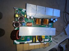
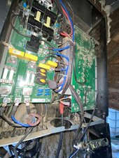
IMG_1201.jpeg

Here's a new main board if needed

Let me know which fuses to check before installing a new board

Could it be the part that accepts the 48 volt system, and feeds it to the main board? That component would be where the + and - terminals connect on the bottom

thanks

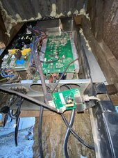
Took it apart

image.jpg

took off the PV input board

image.jpg

Up close of the connectors from small board that accepts the 48 volt connection, going to the main board, those are the two rails that go to the main board, they look fried

1st plan before changing board: unbolt those connectors, hit it with wire wheel and polish it, then see if she reads proper voltage

image.jpg

Main connectors on the main board, fried, took awhile to get the bolts off, burnt everything
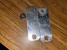
image.jpg

One of the most important connectors, the metal is very low quality

Plan: hit the area with wire wheel on dremel, polish it, put the 48 volt leads directly onto the main board, then melt solder onto that area since there is no way to screw the nuts back onto those bolts
 
Last edited:
Also, I would like to get away from this brand, and get something american made that can be worked on / fixed. Its ok if it is less wattage.

What brand inverter has components that are easier to maintain, american made?

I wish they were more mechanical/traditional, and less tech/sensors/computers/etc
 
Judging from the amount of dust in your Sungold AIO from the pictures I would guess this unit is mounted in a moving vehicle and it is taken Off road fairly often. I would wager that the bolts/nuts for your battery input got loosened from vibration and started arcing until they created the melting condition.

These units are not really designed for mobile conditions or harsh environments. The only company I know that caters to the RV/boating crowd is Victron and they are not American made.
 
What is yalls recommendation to:

Fasten the positive and negative terminals to the main board since those bolts are stripped?

I'm thinking: put a ring on the electrical wires, put those rings in the stripped terminals, then use solder to secure those connections

That area gets super hot, I dont know if it will hold

My plan: solder on the terminals, leave it open and try to run it and see if it picks up proper voltage

Then if it doesnt, then I will install the new board
 
I would attempt to test operation with a simple connection before trying for a permanent one. If the board is fried there is no reason to go to a lot of effort to hook up the battery input. Likely for testing you could get away with a couple of spring clamps. BTW. you would not load the AIO during this testing.
 
I would attempt to test operation with a simple connection before trying for a permanent one. If the board is fried there is no reason to go to a lot of effort to hook up the battery input. Likely for testing you could get away with a couple of spring clamps. BTW. you would not load the AIO during this testing.

Yes, exactly what I need to do, I'll polish it clean, put a simple wire just to see if the connection is even functioning
 
Hit the terminals with wire wheel on dremel

image.jpg

image.jpg

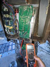
I’m gonna cut out some stuff in the way, hit it with compressed air, rig it back up to the 48 volt batteries, and see if she still has a good board…

IMG_1267.jpegIMG_1265.jpegIMG_1266.jpeg

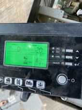
Yes, it is back on, putting out 120 VAC, and is reading the proper voltage, but error code 1 is flashing, I'll check what that code is

Yes, fault code 1 is fan lock, I did remove the fans, makes sense

What is yalls recommendation for:

Installing 2 gauge wires onto the main board in that tight spot?

My idea: anchor the wires in position to the frame of the inverter so they stay put, put both terminals onto the plus and minus, then wrap copper on the bolt that is stripped, then solder it tight

Let me know yalls ideas for anchoring the wires to the motherboard with bolt stripped

Another idea: Put the terminals in onto the plus/minus, get a wire nut that will go around the stripped bolt, also use a washer, the wire nut will push down onto the washer and clamp down onto the terminal, then melt solder onto that area, and the wire will be secured onto the frame of the inverter so it cannot budge, let me know the solder to get from amazon
 
Last edited:
No PV input

IMG_1269.jpeg

Rigged it back up, 120 vac output

PV input not working

I must’ve forgot to hook something up
 
If you have a soldering iron big enough to solder onto those bolts (it will need to be BIG) then it's likely big enough to un-solder from the board, drill out the stripped bolts, and install new ones.

If you are mobile use locking nuts (the all-metal ones not nylok if that area gets more than warm).

Do a proper job for a carefree future :)
 
If you are mobile use locking nuts
wow that is a really good idea, I know what you are talking about

they are nuts wtih thread on the bottom, but the top part has this plastic to tighten the nut in addition to the thread

I dont know the size, but I can get an assortment, hopefully one of them works

The bigger problem now: I am pretty sure I connected the PV board but

There is no PV input

I will diagnose it more tomorrow and make sure there is voltage at the PV input with meter, then

go through all the harnesses and make sure the PV board is plugged in

Only problem I took out components and dont know which harness goes to where

Also, maybe if the fans are disconnected, it cannot take in PV

Someone probably knows, I'll figure it out
 
Only problem I took out components and dont know which harness goes to where

Next time, take lots of photos from all angles, it's not like the olden days when photos cost money. I take millions of "before" photos and even then occasionally miss where something goes :(

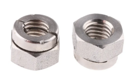
For the lock nuts the "nylok" you describe are great so long as stuff doesn't get particularly warm.

For hot bits there are all metal "aerotight" nuts, they look like this: -

1718250298218.png
 
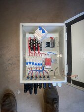
Combiner box fried

IMG_1270.jpeg

Turns out that there was no voltage at the inverter, so I went to the combiner box to see what was happening

0 voltage at the combiner box

Took out wires from one set of panels, 225 volts, hmm...

Messed with the switch on the combiner box, started to hear cooking

I saw some smoke, and some heating elements getting red, and a smell

Cooked combiner box

I understand there is too much solar power for this combiner box

I want to connect maybe one or two sets of panels, but there is no way now since the voltage is high and there is no way to turn off the panels, I might have to wait til night time

Let me know if yall got a way to safely connect one or two sets of panels

Also, I want to get away from the combiner box, it seems like another weak point

What if I connected all the panels in parallel then one line going to the inverter

Let me know flaws of this idea

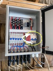
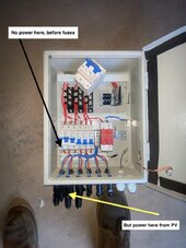
IMG_1270.jpeg

The problem is the fuse that is circled in yellow

I want to bypass that fuse, plan: turn off all six inputs, make sure there is no voltage, take out that bad part circled in yellow, then get a bridge and connect the two areas (white arrow)

Just run 1 or 2 sets of panels in the meantime while you figure out the permanent plan

Let me know if this is a good idea: Put all six sets of high voltage panels wired in parallel, onto a huge fuse holder (150 amp), then run 6 gauge positive and negative to the inverter

Now: I go try to bypass the circled part
 
Last edited:
Your combiner box shows 6 string inputs. The MC4s appear a bit strange there. Are they fused MC4's? The wires going to them do not appear to be standard PV wire. With six in parallel the amperage will be fairly high. If you need to parallel this many strings a combiner box is certainly the correct way to go rather than Y-connectors that could not carry the amperage.

It makes me wonder what is your solar panels arrangement and their specifications. Disconnecting the individual panels at their MC4's should pose little risk if there is no loading.
 
It makes me wonder what is your solar panels arrangement and their specifications. Disconnecting the individual panels at their MC4's should pose little risk if there is no loading.

Yes, I'll turn them off at the 6 individual fuses and make sure there is no voltage before touching the bad part, I'll figure it out

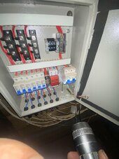
IMG_1271.jpeg

Disconnected wires from the broken fuse, but cannot get the fuse switch off without further disassembly

next step: disconnect all the solar from the panel completely, take panel apart more to remove that area and rig those two sets of 6 gauge wires together, then plug solars back in, and turn on 1 or 2 sets, it should be fine

Update: There is high voltage coming in from the solar panels

There is no power even making it to the first fuse connection, meaning

Just from where the PV connects to the bottom of the combiner box, power is lost

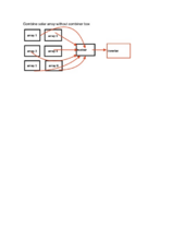
What do yall think of this plan:

combine solar array parallel.png

If I take 6 arrays, and run them parallel into busbars, then run one big positive and negative to the inverter, what is the flaw in this setup?

Is it bad for the arrays to have access to each other?

Tonight: completely get away from the combiner box, combine 1 set of array, connect those to the line going the inverter, and we'll see what happens
 
Last edited:
If you need to parallel this many strings a combiner box is certainly the correct way to go rather than Y-connectors that could not carry the amperage.

Yes I understand. It would put too much amperage on one circuit, they have to be separated using combiner box

IMG_1277.jpeg

Removed combiner box

IMG_1278.jpeg

The problem: combiner boxes from Amazon have cheap components and it burned the main fuse. That main fuse in the picture that is removed, tried to switch it back and forth, it wont stay on, I guess the main fuse is burned

While I figure out the combiner box solution, I will run 1 or 2 sets into the inverter. If I decide to run 2 sets, can I hook them up parallel and it wont be too much amperage for that circuit?

Also bigger picture: what is the solution in this situation?

1. Fix the current combiner box, and get a second combiner box since there is too much electricity, run half the array to one, and another half to another

2. Build a custom one that can withstand big electricity, with name brand fuses, not ones that are cheap/low quality

Let me know which way yall would go, tonight, I will hook one set of panels up just to at least generate some electricity

It is one set of panels out of 8 set of panels
 
Last edited:
Yes what exactly is needed to make this happen
A box, preferably rated for the application.
Din rail.
A suitable mounting location.
Quality Din mount DC Rated fuses for the appropriate voltage and amperage.
Quality Din mount DC Rated breakers/disconnects for the appropriate voltage and amperage.
Quality wire for the appropriate voltage and amperage.
A surge protection device, such as midnite for the appropriate voltage.
A proper grounding system.
Ferrules of the appropriate size for the wire.
Ferrule crimpers sized appropriately for the wire.
Wire cutters.
Wire strippers.
Screwdrivers of the appropriate size for the fasteners.
A multimeter.
Time.
Understanding of how to wire components.

That should about cover it, I'm probably missing a few things depending how exact you need.
Yes, I need to understand how it works. Conceptually speaking, it is one way electrical circuits all going into one main central receiver, then that goes to the inverter

Ill look at the one that broke, and try to understand it

Simply speaking, is there way to make electricity go one way?

Is this possible:

solar array (200 volt) -> (a one way breaker) -> inverter

If someone can link a product I can examine, or a name of the component, that would help

IMG_1278.jpeg

this is what was frustrating about this box, there was PV power at the bottom, but NO power at even the first fuse. Something is off in that unit, and it was causing more confusion. That main fuse, it sounds like broken glass inside (fried).


Here’s one that might work, midnite solar does offer a high amp combiner box

I have to read and figure out which one works

My system: 8 strings of 200 volt arrays, each one producing 10-15 amp max

Let me know which one is capable of handling this system
 
Last edited:
Yes, I need to understand how it works. Conceptually speaking, it is one way electrical circuits all going into one main central receiver, then that goes to the inverter

Ill look at the one that broke, and try to understand it

Simply speaking, is there way to make electricity go one way?

Is this possible:

solar array (200 volt) -> (a one way breaker) -> inverter

If someone can link a product I can examine, or a name of the component, that would help

View attachment 222161

this is what was frustrating about this box, there was PV power at the bottom, but NO power at even the first fuse. Something is off in that unit, and it was causing more confusion. That main fuse, it sounds like broken glass inside (fried).


Here’s one that might work, midnite solar does offer a high amp combiner box

I have to read and figure out which one works

My system: 8 strings of 200 volt arrays, each one producing 10-15 amp max

Let me know which one is capable of handling this system
Here's a photo of my first one when in was putting my system together.
Post in thread 'Not sure how to wire' https://diysolarforum.com/threads/not-sure-how-to-wire.70037/post-885984

More photos here.
(Wow its crazy how my system has evolved)
Some more info about it here.

Midnite makes a solid product.
 
Midnite makes a solid product.

Does midnite solar use quality circuits or are they the same as the one I had?


This is the one that burned, in the reviews, people saying it cannot handle more than 225 volts, my system is 225 volt

I dont understand how to build it myself, it would be much easier for me to get one assembled but with LEGIT electronics that can handle high voltage (225 volt)

I'll look through them now and see the exact one that will be used for this system

Image 6-14-24 at 10.47 PM.jpeg

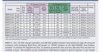
here is their spec sheet, which one works with 8 strings of 225 volt, 10-15 amp max each string?

I am thinking MNPV12 HV since that one accepts 600 volt input, and can handle 200 amps of current

This should be enough right? Or get the MNPV16 (HV) since that one handles 240 amps of current

The system is very powerful and I do not want to keep servicing it, I want something that I do not have to keep fixing/diagnosing

I'll look now and see the cost of those units

hmm, from what I am seeing, they only sell the enclosure, I still have to figure out the breakers etc

I'm now watching youtube videos of how people do it


Ok here is a midnite solar combiner, prewired, can handle up to 600 volts, and can put out 200 amps..

Will this one work perfectly for this application?

I have been searching maybe to put together one myself, I am studying how they are put together but basically:

solar -> high voltage breaker (15 amp) x8, they're on a rail

Then, take big wire from that and go to the inverter

Are there quality high voltage DC breakers made my square D or trusted brands?

Midnite solar sells those breakers for $50 a piece, it would be cheaper just to get the one already put together


thanks yall
 
Last edited:
Does midnite solar use quality circuits or are they the same as the one I had?
Quality. They've been around a while and are known for quality and reliability.

This is the one that burned, in the reviews, people saying it cannot handle more than 225 volts, my system is 225 volt

I dont understand how to build it myself, it would be much easier for me to get one assembled but with LEGIT electronics that can handle high voltage (225 volt)

I'll look through them now and see the exact one that will be used for this system

View attachment 222176

here is their spec sheet, which one works with 8 strings of 225 volt, 10-15 amp max each string?

I am thinking MNPV12 HV since that one accepts 600 volt input, and can handle 200 amps of current

This should be enough right? Or get the MNPV16 (HV) since that one handles 240 amps of current

The system is very powerful and I do not want to keep servicing it, I want something that I do not have to keep fixing/diagnosing

I'll look now and see the cost of those units

hmm, from what I am seeing, they only sell the enclosure, I still have to figure out the breakers etc

I'm now watching youtube videos of how people do it


Ok here is a midnite solar combiner, prewired, can handle up to 600 volts, and can put out 200 amps..

Will this one work perfectly for this application?

I have been searching maybe to put together one myself, I am studying how they are put together but basically:

solar -> high voltage breaker (15 amp) x8, they're on a rail

Then, take big wire from that and go to the inverter

Are there quality high voltage DC breakers made my square D or trusted brands?

Midnite solar sells those breakers for $50 a piece, it would be cheaper just to get the one already put together


thanks yall
Give Midnite a call, I've read they are extremely helpful.

I know Current Connected is extremely helpful and carries Midnite.
They may even go as far assembling everything to your liking.

I would not recommend using one with MC4 connectors.
 
It is something in the inverter

IMG_1282.jpeg

When disconnected from the inverter, I am getting 224 volts

IMG_1283.jpeg

Something is not hooked up properly, ground, signal, bus, something

IMG_1284.jpegIMG_1286.jpeg

In this photo, what are these two wires I am pointing to? Maybe I hooked them up backward, I cannot see where they go into the motherboard, I just remembered that the longer wire goes to the further connection

IMG_1287.jpeg

No Pv power once wire connected to the PV input on the inverter

I will go study the old pictures and see if maybe I can find the problem

Another potential problem: the fans are not hooked up and putting up fan fault, maybe it is designed for:

If fans are not hooked up, it will not take in PV for safety...

Hooked up the fans, now there are no fault codes, but, still no PV input

From what i see, everything is connected

I need to set aside a real effort, organize the area, and really try to figure out the issue
 
Last edited:
Preface: for a small system with a few panels, this unit works fine, but this current situation that burned it: 36 panels, pulling 3k for 8 hours a day, sometimes will pull 4-5k watts and that will shut the machine down from overheating, I always kept the setting that did not let the machine pull more than 80 amps of PV because the solar is so strong, but still this happened

This is the problem with the Chinese inverters, they may work for a bit and you will let your guard down and think everything is OK

Then when you have problems, you need to become an expert to figure it out/fix it

And you can do more damage to the unit if you take it apart improperly, there are tons of little harnesses

Thats why big picture, the better thing to do, is just get the american made inverter that cost 5 times as much

Because I bet when they break, they are easier to fix, and they break less often

The Chinese inverter is packed with so much extra metal/unnecessary components, that the thing cannot breathe and it is bound to break

The sad part: if they just would have made that component going to the 48 volt battery system more robust, then maybe this would not have happened

That metal they used might be the LIGHTEST metal I have ever touched, and that is where ALL power is coming and going, since

It sends power to 48 volt from the solar, and pulls power from the batteries to convert to 240 VAC for household use

They could eliminate tons of the BS components, and just installed a STRONG, LARGE copper connection to spread the heat of that point

Now, I need to go there, take it all apart, live wires all over the place, tinkering with it...

I am over it, I wish midnite solar made a small but reliable inverter that doesnt cost $5000, and I wish I would have gone with that one

Later on, once I go tinker with the inverter, I want to talk to yall about skipping the inverter, the route would be:

Solar power (200 volt) -> AC unit, or if we cant go direct from solar current to the AC unit, then:

Solar power (200 volt) -> Charge controller -> 48 volt battery system, 48 volt AC unit

Meaning, if they are mainly needing the solar for Air conditioning, can I install for them an AC unit that runs on direct current,

I do see them for sale but for big cost

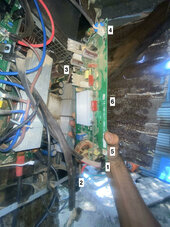
pv board.jpeg

Ok here is the PV board removed, connections:

1. that 8 prong harness
2. PV wires from panels
3. 2 wire small harness, goes to main board
4. 2 wire harness goes to main board
5. 2 wire harness goes to main board
6. Front two black wires, I cannot see where they go to on the main board, but they could be mismatched, I just remember putting the longer onto the further connection

let me know if there are any other connections on the PV board that I missed

Thanks
 
Last edited:
You do realize your mounting and using an INDOOR ONLY all in one OUTDOORS right? It was never designed to be subjected to those humidity levels and dirt levels. I'm amazed lasted as long as it did. Ive had mine (which looks like the same tp6048 model I have) for over a year now running my entire house with zero issues with powering the house and it still looks like new inside and out.

There are units designed to work outside like that but this is not one of them.
 

diy solar

diy solar
Back
Top