diy solar

diy solar

Connecting several hybrid inverters to one battery - Manufacturers position

I answered the question in post #7.
Indeed, I saw it, but just saying yes it will work is difficult to interpret.

You haven't said if its an assumption on your part, do you know it for a fact and if yes, how so? Do you use such a setup yourself, or do you know someone with it? Or perhaps you have good knowledge of the electronic architecture of these things which lets you say with authority "yes, it will work" in which case some description of the circuit with justification would be nice...

In short, it is most helpful to give more detail when answering questions that has potential to cause very expensive damage. Otherwise anyone following said advice is risking a case of "I blew up my inverter because a guy online said so".

I gave my "informed" guess in posts #5 and #9
Thanks.
 
I did elaborate in subsequent posts.

Never trust a random guy online.
always do your own research on everything.
 
I did elaborate in subsequent posts.

Never trust a random guy online.
always do your own research on everything.
OK, You said:
Connecting multiple loads (inverters) to a source (battery) is not a problem. As long as the source can handle the loads.
Since your inverters are completely separate from each other. All that they are, is a load on your battery.
How do you know for a fact they are "just a load", by definition they are not if both AIOs are capable of charging. If so, why is the battery voltage being pulled down with regards to earth be half of its potential? You also replied this is just a potential difference and not able to supply any current. On what basis? I haven't seen an answer.

A typical AIO sold today has a HV DC bus and a battery is connected by a bidirectional non-isolated DC converter. Do you know enough about how these converters work to be able to say so? Can you elaborate?

Edit: Anyone researching the topic from electronic perspective will find the attached very useful.
 

Attachments

  • ysf.2016.7753752.pdf
    1,007.9 KB · Views: 4
Last edited:
OK, You said:

How do you know for a fact they are "just a load", by definition they are not if both AIOs are capable of charging.
Max draw and max charge. Don't exceed those, and you are fine.

One can charge with comms, and one by voltage, or both by voltage. Not any different from having multiple charge controllers on a battery bank.


If so, why is the battery voltage being pulled down with regards to earth be half of its potential?


??? Don't know what you are asking.

If each inverter draws max 1/2 of the battery max draw, then when both draw at max, you are not exceeding the limit.

You also replied this is just a potential difference and not able to supply any current. On what basis? I haven't seen an answer.
 
For high voltage Hybrids, never connect more than one inverter to a battery bank, it is non-isolated connection and magic smoke will come out.
 
I'm planning to install several hybrid inverters and connect them to one battery. Each inverter has its own solar array and own AC load. The purpose of the battery is to store excess energy and therefore to share the solar power between inverters (consumers). I've read all discussions here and they all generally support connecting two inverters to one battery. However, the solar systems installers here in the UK refuse to install in such way. They refer to the manufacturers (Sunsynk and Growatt) that do not allow such installation. I need you help to find answers to the following questions:
- Is there any inverters/battery manufacturer that supports connecting several inverters to one battery?
- How can I properly connect the communication cable to BMS? Connecting to one of the inverters? Or through a bus bar?
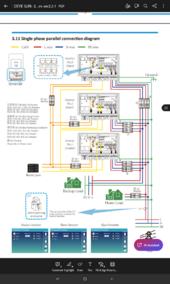
No expert here but I've been looking at a deye manual all day the manufacturer of sunsynk inverters and thought I would post this page.
Screenshot_20240620-195027.png
 
I've read all 3 pages... I still don't know, can I connect a second AIO to the same (very large) battery or not?

...

Can anyone answer the question, or provide an informed guess?
I run 2 completely separate AIO's (Each has their own PV array and AC output) off the same battery bank plus an inverter charger. But mine is dumb and does not have those "smart" talk to each other and the world via internet setups. Obviously those folks that run parallel setups with AIO's run them off the same battery and some of them use communications.

I really wonder what it is that would cause issues. Maybe proprietary equipment has freakout circuitry if you attempt to do things the manufacture suggests you don't.
 
??? Don't know what you are asking.
This refers to my previous post with voltage measurements in relation to ground on battery terminals of two standard non-parallel non-isolated AIO inverters.

I essentially measured - half of battery voltage on minus, and half of the battery voltage on plus. Also some (fairly small but still) AC components.
If each inverter draws max 1/2 of the battery max draw, then when both draw at max, you are not exceeding the limit.
Again. We are not talking about current limits. It is a completely separate conversation. Set both AIOs at less than half of max. Problem solved.

The problem can really be stated as "can two non isolated bidirectional DC-DC converters be hooked up to one power source without synchronising their switching frequencies". And if true for some designs and not others, which?

For high voltage Hybrids, never connect more than one inverter to a battery bank, it is non-isolated connection and magic smoke will come out.
All currently sold cheap low voltage AIOs are non-isolated too. (on the basis of every manufacturer saying not to ground any battery terminals, because damage will result).

No expert here but I've been looking at a deye manual all day the manufacturer of sunsynk inverters and thought I would post this page.
View attachment 223314
These are designed to be paralleled... Not a problem at all. It's not really what this thread is about.

I run 2 completely separate AIO's (Each has their own PV array and AC output) off the same battery bank plus an inverter charger. But mine is dumb and does not have those "smart" talk to each other and the world via internet setups. Obviously those folks that run parallel setups with AIO's run them off the same battery and some of them use communications.
I'm really glad you do :) it is exactly the kind of setup that can be used to verify the possibility without any clever control mechanisms.

Thank you for mentioning it. What make and model are they?

I really wonder what it is that would cause issues. Maybe proprietary equipment has freakout circuitry if you attempt to do things the manufacture suggests you don't.

Looking at the pdf I posted above there are 5 common non-isolated bidirectional DC-DC converter circuit types used in these inverters.

The simplest of these circuits is putting a bank of capacitors in parallel with a battery and a big inductor in series. By putting two such circuits in parallel and connecting go one battery we double the capacitance of that bank available to each AIO to charge their inductors. Naturally the switching frequency of both DC converters in these AIOs will not be synchronised. So if they drift in relation to eachother and consequently the amount of capacitance behind that inductor varies cycle to cycle how is this going to affect the control mechanism? And we haven't even tried charging with one AIO and discharging with the other.

Inductor shouldn't be affected, but the amount of current available to charge them will vary rapidly. If it is only important this value doesn't fall below a certain low threshold, we're fine (it's probably what you're observing). But if the amount of capacitance is already pretty low (IDK the manufacturer decided to save money, or some caps dried up) it may have bad consequences...

And this is only the simplest circuit.

The key is that none if these circuits are isolated so establishing on the basis of theory if it can be dobę or not is very difficult without simulation. That's why practical experiences (and specifying exact make and models) is so important to answer this.
 
...

Thank you for mentioning it. What make and model are they?


...
The two in operation now are both PowMr POW-LVM-24V-H. I previously was running 2 EAsuns 3kW units of similar SRNE manufacture but lower PV voltage capability. Total run time for me is near over 1.5 years with the two AIO's and the last month I added a Ampinvt 5kW Low Frequency Inverter charger that is not being used as charger, strictly battery to split phase output. Also in the mix is a 3rd PV array that feeds the battery from another SCC plus a wired in 12a AC to DC battery charger that is used on a timer circuit for overnight addition if conditions warrant.

Nothing untoward has been noted doing this.
 
The problem can really be stated as "can two non isolated bidirectional DC-DC converters be hooked up to one power source without synchronising their switching frequencies". And if true for some designs and not others, which?
If the AC of two inverters are not connected, then what's the problem? The DC battery doesn't see the AC.

Note: The Inverter does switch on and off draw from the battery. That is what the inverter's capacitors are for. Smooth out draw/voltage from the battery.
 
OK, You said:

How do you know for a fact they are "just a load", by definition they are not if both AIOs are capable of charging. If so, why is the battery voltage being pulled down with regards to earth be half of its potential? You also replied this is just a potential difference and not able to supply any current. On what basis? I haven't seen an answer.

A typical AIO sold today has a HV DC bus and a battery is connected by a bidirectional non-isolated DC converter. Do you know enough about how these converters work to be able to say so? Can you elaborate?
Separate systems connected to a battery (whether charging or discharging), do not affect each other. (the battery being the only common connection)
It only becomes a problem if the systems are also otherwise connected, in a non compatible way.
It's not as complicated as you seem to think it is.
it's just loads and chargers.
 
You also replied this is just a potential difference and not able to supply any current. On what basis? I haven't seen an answer.
Years of experience.
You can't power a load without a "completed" circuit.
Connect a load, and you can confirm this for yourself.
 
Separate systems connected to a battery (whether charging or discharging), do not affect each other.

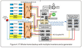
This is dependent on the inverter design, I have actually measured the battery connections in operation and they are at different potentials for the Solis products ( and all HV battery inverters I know of )

This is from the Solis S6 manual and I highlighted the separate battery required. It is a HARD REQUIREMENT

Typically, LV battery ( 48V and lower ) the battery ports have galvanic isolation which would allow ( and is common ) one battery bank for multiple inverters attached.

6-20-2024 1-46-04 PM.jpg

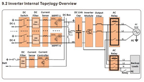
And here from the manual is the S6 Typology

6-20-2024 1-54-40 PM.jpg
 
This is dependent on the inverter design, I have actually measured the battery connections in operation and they are at different potentials for the Solis products
(y) this ^^^^

Typically, LV battery ( 48V and lower ) the battery ports have galvanic isolation which would allow ( and is common ) one battery bank for multiple inverters attached.
... typically maybe, but still depends on inverter design - the Solis S5 LV does not have isolation.

I'll refer @Luk88 back to the link that I already put in posting #17 on page 1 of this thread
 
typically maybe, but still depends on inverter design - the Solis S5 LV does not have isolation.

Agreed, always follow the manufactures installation requirements and never assume anything can be done just because you have done it before with other equipment.
 
This is dependent on the inverter design, I have actually measured the battery connections in operation and they are at different potentials for the Solis products ( and all HV battery inverters I know of )

This is from the Solis S6 manual and I highlighted the separate battery required. It is a HARD REQUIREMENT

Typically, LV battery ( 48V and lower ) the battery ports have galvanic isolation which would allow ( and is common ) one battery bank for multiple inverters attached.

View attachment 223380

And here from the manual is the S6 Typology

View attachment 223382
High voltage batteries in parallel inverter systems are a completely different animal.
But for separate systems the battery voltage isn't significant. As long as both systems are matched for the voltage.

Edit:
The point being that paralleled inverters are not separate.
 
Agreed, always follow the manufactures installation requirements and never assume anything can be done just because you have done it before with other equipment.
That's exactly the point of me reviewing this thread. Every single manufacturer of these new cheap AIOs implies their LV battery inputs are non-isolated (by putting a huge warning about grounding any battery terminal). Sadly just asking them is the worst thing you could do. I recently asked my "manufacturer" about a cooling issue with an inverter. I sent them a picture showing transparent air ducting inside and I asked if something is not missing. You know what they replied...
"um, don't need this plastic.[Sweat]". Completely clueless... If the goal was for this to be the last tech question I asked, they achieved it.

The two in operation now are both PowMr POW-LVM-24V-H.
Great. I checked, the manufacturer says "no parallel capability". This is very useful.
I previously was running 2 EAsuns 3kW units of similar SRNE manufacture but lower PV voltage capability.
Did you have them connected like this too? Do you perhaps remember which EASUNs were they? (this is of special interest to me as I have an EASUN SMH-ii).
Total run time for me is near over 1.5 years with the two AIO's and the last month I added a Ampinvt 5kW Low Frequency Inverter charger that is not being used as charger, strictly battery to split phase output. Also in the mix is a 3rd PV array that feeds the battery from another SCC plus a wired in 12a AC to DC battery charger that is used on a timer circuit for overnight addition if conditions warrant.

Nothing untoward has been noted doing this.
This is very valuable info for anyone looking for an answer. Thank you.

If the AC of two inverters are not connected, then what's the problem? The DC battery doesn't see the AC.

Note: The Inverter does switch on and off draw from the battery. That is what the inverter's capacitors are for. Smooth out draw/voltage from the battery.
This is the key to understanding what I'm talking about. The Inverter exactly switches on and off it's connection to the battery as you said. It does so very quickly with timing depending on its control loop. The other end of this "switch" is connected to inverter's internal high voltage DC bus (~400V).

So how does the low battery voltage gets boosted to 400V?

There are various designs, but the simplest also has an inductor in series with "the switch". Long story short when you do this and you "switch on" the inductor charges up - a bit like a capacitor. Then when you switch off it tries to continue pushing the same current raising the voltage. By controlling the timing, capacitance and inductance you control the voltages and currents. And we haven't even started talking about charging - it's the same circuit that does this, so current can flow in or out. Now imagine you have two such circuits with completely unsynchronised switching messing with eachother.

I'm not saying that's what happens as @MattB above has been running the types he's got for some time. I'm just saying there is possibility of problems so we better gather the reports from people that do run like this with makes and models of their inverters to be sure. @SeaGal 's experience with the 100ohm resistor is enough to show that no, it is not "as simple as loads and chargers".

There are many AIO designs out there. The pdf I attached shows 5 most common non-isolated ones. Putting out a blanket statement like "all of them are fine to parallel on the battery side, it's just loads and chargers" without saying something like "I've been installing them in parallel for years" and list some types. Or taking one if these common designs and justyfying using EE principles is just dangerous.

And answering a question how do you know something with "years of experience"(unless you're a designer of said AIOs, or an EE university professor) is a huge red flag to take anything else said with a (large) grain of salt.

You can't power a load without a "completed" circuit.Connect a load, and you can confirm this for yourself.
When the switching elements in the DC converters are on there is a complete circuit.

High voltage batteries in parallel inverter systems are a completely different animal.
Indeed, but here is an example of one that is parallell both on AC and DC side from Deye (HV battery).
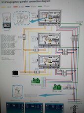
Compress_20240621_092030_0538.jpg
What does this prove? That there are kinds of HV inverters that can and cannot share the same battery - at least among ones that can be parallel'ed on the AC side.

But this thread is really about low cost low voltage non-isolated AIOs with no parallel function on the AC side. So no Deye etc, and no HV.
 
But this thread is really about low cost low voltage non-isolated AIOs with no parallel function on the AC side. So no Deye etc, and no HV.
Op's 1st post literally said connecting multiple aio's to one battery and that sunsynk apparently told him he cannot, deye is technically sunsynk so I'm inclined to think you have misunderstood the topic and just want to argue with others. OP hasn't made a single post since he started the thread nor did he define that each inverter shouldn't be paralleled or use separate loads. I'm guessing the 4 pages of advanced information that might not pertain to his question and arguments might have scared him off.
 
Op's 1st post literally said connecting multiple aio's to one battery and that sunsynk apparently told him he cannot, deye is technically sunsynk so I'm inclined to think you have misunderstood the topic and just want to argue with others.
Which part of it did I misunderstand? That sunsynk is Deye and therefore this thread is about "expensive" AIOs? Yes, I didn't know that Sunsynk is Deye. If op stated he needed advice with a specific AIO type (rather than just saying Sunsynk/Growatt) I probably would've started my own thread with a more general question.

Do I like to argue? No, but I like to get to the bottom of things.

If asking people to support their claims with something more than "years of experience" is argumentative than there is no shame in that.

Also we had actual first hand evidence to the contrary from two people. One, who had one of his AIOs go poof when it started charging(perhaps it was a failure of one of the units, perhaps it is a design fault that precludes using a single battery with this type - @timselectric indicated he knows for sure it was a unit's fault). The other measured HV bus potential on the battery and later unsuccessfully tried to discharge it with a 100ohm resistor causing a large spark suggesting caps across the battery were actually charged to that potential with reference to ground at the very least.

We also had very good info from @MattB specifying his exact setup, and that it works. And for these particular inverter types (and probably his earlier EASUNs) the matter is settled for me.

We know it for a fact one can use a common battery with isolated DCDC converters (transformer based), but what about the non isolated transformer less(in the battery converter, not in the inverter part) designs that are more and more popular today?

OP hasn't made a single post since he started the thread nor did he define that each inverter shouldn't be paralleled or use separate loads. I'm guessing the 4 pages of advanced information that might not pertain to his question and arguments might have scared him off.
He literally said they will have their own separate loads in the very first sentence....
 
He literally said they will have their own separate loads in the very first sentence....
Sorry didn't see that but my point still stands op hasn't come back to explain his choices or ask any further questions. I've not agreed with tim before but rather than keep arguing on a public forum with a person I don't know, I've chosen to not get into some heated debate in a thread with someone who obviously has plenty of his own experience.
 
We know it for a fact one can use a common battery with isolated DCDC converters (transformer based), but what about the non isolated transformer less(in the battery converter, not in the inverter part) designs that are more and more popular today?
It's doesn't matter if the DC to DC converter is isolated or not, if the two separate systems are isolated from each other. (Except for the battery)
There's no path for current to flow anywhere it shouldn't.
 
It's doesn't matter if the DC to DC converter is isolated or not, if the two separate systems are isolated from each other. (Except for the battery)
There's no path for current to flow anywhere it shouldn't.
But they aren't isolated from eachother. What about the grounding they share? It has been demonstrated battery terminals of some inverters have various (sometimes pretty high) potential in reference to ground. This potential has to equalise if you connect two in parallel so current must flow. Is it going to harmless micro amps or lots of current? @SeaGal 's experiment with a 100ohm resistor trying to ground one of the DC battery terminals and getting a large spark (plus a fried canbus device connected to the same battery) tells us few things. Either capacitors were charged over a long time to such high voltage (with ref to ground) or the DC converter used in that device is perfectly capable of sending high voltage with substantial current from its DC HV bus to the battery.

Sorry didn't see that but my point still stands op hasn't come back to explain his choices or ask any further questions. I've not agreed with tim before but rather than keep arguing on a public forum with a person I don't know, I've chosen to not get into some heated debate in a thread with someone who obviously has plenty of his own experience.
Are we having a heated debate? Yes, but is it arguing? I don't think so. A purpose of "arguing" is to demonstrate the other person don't know what they are talking about. I don't care about doing that. Anyone can make up their own mind. If I thought @timselectric was 100% completely wrong I wouldn't even reply beyond stating that. I did/do to find out more about his reasoning.

Coming back to the point of this thread.

I've been reviewing service manuals for Voltronic AIOs with a HV DC bus and LV batteries (both ones that can and cannot be paralleled according to the "manufacturer) and it appears there are two common battery converter designs. One uses a single large transformer, the other has two. I haven't had time to trace the designs to see if that single transformer circuit is indeed isolated (it's just claimed not to be by various clueless clone makers), or is it just being used as in diagram F and G in the pdf showing non-isolated circuits linked before(page 3).
 
I would like to chime in here. I have concerns about two inverters using the same battery without comms.

Complete off grid.

I had a growatt 5000es hooked up to my generator charging my 48v battery( only using as charger) no AC output hooked up at all. Just Genny. Breaker. Battery bank. On the same battery I had my solark 15K hooked up powering my house loads. Reason I did this is to avoid flickering lights in the house when Genny on. Worked great UNTIL one morning I was charging with this setup and solar started producing. As soon as solar power coming into solark (again NO solar hooked up to growatt). As soon as solar soming into solark overtook the loads in house and started also charging the batteries. pOOF. Fried the growatt. Tripped my breaker. Tripped all my BMS for over current and shut everything down.

I have a thread about it you can search.
I have had great success using multiple inverters, batts and SCCs on two separate systems. My 24v system has 4P batts, 3 inverters and 8 charge controllers. My 12v system has 2 inverters, 8 charge controllers and 8P batts. All works amazing BUT, I have zero AIOs, everything is independent and zero comms.

You really don't need comms, it just complicates things. I think its better without unless you want a good centralized monitoring.
 
But they aren't isolated from eachother. What about the grounding they share? It has been demonstrated battery terminals of some inverters have various (sometimes pretty high) potential in reference to ground. This potential has to equalise if you connect two in parallel so current must flow. Is it going to harmless micro amps or lots of current?
Unless the equipment is faulty, it should be minimal.
A typical static discharge at most. That immediately falls to zero.
@SeaGal 's experiment with a 100ohm resistor trying to ground one of the DC battery terminals and getting a large spark (plus a fried canbus device connected to the same battery) tells us few things. Either capacitors were charged over a long time to such high voltage (with ref to ground) or the DC converter used in that device is perfectly capable of sending high voltage with substantial current from its DC HV bus to the battery.
You should never connect either DC positive or negative to ground, unless the manufacturer specifically instructs you to do so.
The only systems that I know of that are still setup for that, are geared towards the mobile and marine environment. Victron , is the first that comes to mind. But there are probably others.
Are we having a heated debate? Yes, but is it arguing? I don't think so. A purpose of "arguing" is to demonstrate the other person don't know what they are talking about. I don't care about doing that. Anyone can make up their own mind. If I thought @timselectric was 100% completely wrong I wouldn't even reply beyond stating that. I did/do to find out more about his reasoning.
I don't argue with people online. Life's too short.
If I thought that we were arguing, I wouldn't still be in the conversation.

I've been reviewing service manuals for Voltronic AIOs with a HV DC bus and LV batteries (both ones that can and cannot be paralleled according to the "manufacturer) and it appears there are two common battery converter designs. One uses a single large transformer, the other has two. I haven't had time to trace the designs to see if that single transformer circuit is indeed isolated (it's just claimed not to be by various clueless clone makers), or is it just being used as in diagram F and G in the pdf showing non-isolated circuits linked before(page 3).
The only way that I can see that there could be an issue.
Is if one of them had an internal connection between positive and ground. And the other had an internal connection between negative and ground.
I would expect this to be highly unlikely, but anything is possible.
 

diy solar

diy solar
Back
Top