diy solar

diy solar

JK BMS RS485 Communicate Protocol Manual

Familymandan

New Member
Joined
Dec 11, 2020
Messages
25
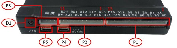
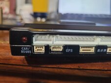
Hello, I am looking for the JK BMS RS485 Communicate Protocol Manual. I am wanting to use the RS485 port to communicate with my PLC (Programmable Logic Controller). Via RS485/Modbus, Master/Slave.
I already communicate with my Sigineer Inverter and (5) Solar Charge Controllers this way.
I attached the Sigineer manual as an example.
OR, does anyone have a good tech support contact for JK BMS?
 

Attachments

  • Sigineer-Power-Inverter-Charger-RS232-Communicate-Protocol.pdf
    255.3 KB · Views: 36
  • Sigineer-Power-Inverter-Charger-RS232-Communicate-Protocol.pdf
    255.3 KB · Views: 27
I think it is this one.
 

Attachments

  • BMS-RS485Communication protocol.pdf
    689.4 KB · Views: 69
Thank you so much tinyT
I just found another one that is the same thing w/o the NEEY printed on it.
Have you tried this?
 

Attachments

  • JK BMS Comm Protocol.pdf
    700.4 KB · Views: 54
Thank you so much tinyT
I just found another one that is the same thing w/o the NEEY printed on it.
Have you tried this?
Using a hex terminal utility program.
 

Attachments

  • JK BMS test.txt
    2.3 KB · Views: 33
Wow!. This is good stuff. Thank you. I'm very new here and don't know how this forum stuff works really.
Should I start a new thread just for code?
I have to write code to communicate with all 3. Sigineer, SunnySky, and JK BMS.
 
You started this thread, you can put it here. Or start another one. As long as it's not a bunch of duplicate stuff, everything pretty much goes.
 
Wow!. This is good stuff. Thank you. I'm very new here and don't know how this forum stuff works really.
I'll reply, and maybe start a new thread about code. I'll have code written for all 3. Sigineer, SunnySky, and JK BMS.
 
Hello again,
Can anyone tell me where to get the P4 (GPS/RS485) connector w/flying leads
 

Attachments

  • JKBMS Connections.jpg
    JKBMS Connections.jpg
    81.2 KB · Views: 10
I think somebody posted this link in this forum, I don't remember now so CTTO.
Pick the 4P.
 
That's good info, thanks. Does anyone know what the pitch is?
 

Attachments

  • JKBMS Connections pitch.jpg
    JKBMS Connections pitch.jpg
    8.6 KB · Views: 7
I just purchased a new JK-B2A24S-15P and the connectors are different. This is a 3 pin. But a different style? Does anyone know this type?
 

Attachments

  • 20240621_092308.jpg
    20240621_092308.jpg
    145 KB · Views: 1
I just purchased a new JK-B2A24S-15P and the connectors are different. This is a 3 pin. But a different style? Does anyone know this type?
I don't know what interface you want to use. This is from the JKBMS Instruction document.
6-21-2024 7-27-35 AM.png
Note "GPS" VCC is battery voltage not 3.3v. Also, I think the pitch for GPS is 1.25mm. I don't know the pitch and connector style for CAN/RS485.
 
Yep met the same brick wall, searched around for hours trying to identify these pin sockets - not in JST range - specials?

If you get a problem with damage this may be serious grief. They are very small ca 1mm and seem fragile. I was looking to find spare plugs with flying leads to make a break out board to convert to std jst 2.5s nice an robust and common use.

Anyone any ideas? Contact jk to buy a spare set of leads? - silly idea?
 
It's a JST NSH connector: https://www.jst-mfg.com/product/pdf/eng/eNSH.pdf

Look for NSHR-03V-S
OH WOW I spent ages looking for that pce. thnx 10^6 @upnorthandpersonal

To summarise

NSH-03V-S = CAN bus - 3pin
= GPS RS485 - 4pin
NSH-06V-S = LCD (and reset sw)
NSH-07V-S = Heater

What does GPS mean? What connector is it?
FWIW

but these are just the plastic housing, you need the crimp leads as well 1.0mm type - there's a challenge

This is what I found but you need the crimp connector as well 1719061317012.png
 

Attachments

  • image_2024-06-22_134346907.png
    image_2024-06-22_134346907.png
    877.3 KB · Views: 3
  • image_2024-06-22_134519931.png
    image_2024-06-22_134519931.png
    513.5 KB · Views: 2
  • image_2024-06-22_140126960.png
    image_2024-06-22_140126960.png
    232.3 KB · Views: 2
What does GPS mean?

As in navigation. These BMS were originally intended for things like e-bikes as well, and can be equipped with a GPS/cellular module for location tracking. For clarification: the BMS does not have a GPS module inside, but it can be added with this connector.

The connector for that one is a JST 1.25mm (SH series iirc).
OK thanx GPS tracking - of your solar batteries who da thought it, and using these bms on an Ebike (scooter? ones that burst into flames, what do I know?) thanx for the heads up

FWIW as another member said, these jk bms are so cheap vs cost of prismatic bank, that you can afford a spare
 

Attachments

  • image_2024-06-22_150618143.png
    image_2024-06-22_150618143.png
    109.9 KB · Views: 1
OH WOW I spent ages looking for that pce. thnx 10^6 @upnorthandpersonal

To summarise

NSH-03V-S = CAN bus - 3pin
= GPS RS485 - 4pin
NSH-06V-S = LCD (and reset sw)
NSH-07V-S = Heater

What does GPS mean? What connector is it?
FWIW

but these are just the plastic housing, you need the crimp leads as well 1.0mm type - there's a challenge

This is what I found but you need the crimp connector as well View attachment 223766

Maybe this will work.

Buy 2 to make 3 or 4 pin NSH connector. Cut the wire in the middle and crimp/solder whatever connector you want at the cut ends
 
Maybe this will work.

Buy 2 to make 3 or 4 pin NSH connector. Cut the wire in the middle and crimp/solder whatever connector you want at the cut ends
Maybe this will work.

Buy 2 to make 3 or 4 pin NSH connector. Cut the wire in the middle and crimp/solder whatever connector you want at the cut ends


Indeed Digikey and looks like a source but OMG total cost inc shipping (£12) inc tax ca £20 for some tiny wires. As one member said, better to buy a new jk bms unit. I would struggle to handle such tiny crimp components with tweezers. All good to know what we are dealing with in case of trouble - So TAKE VERY GREAT CARE OF YOUR BMS CONNECTORS.
 
I'm still confused. One pic shows CAN/RS485. One pic shows GPS/RS485. Which is the RS485 port? It appears the GPS port is actually RS485? And exactly what connector is needed for the correct RS485 port? Of course I've emailed JK several times to no avail.
 

Attachments

  • JKBMS Connector Layout.png
    JKBMS Connector Layout.png
    347.1 KB · Views: 5
  • JKBMS Connections.jpg
    JKBMS Connections.jpg
    81.2 KB · Views: 5
I'm still confused. One pic shows CAN/RS485. One pic shows GPS/RS485. Which is the RS485 port? It appears the GPS port is actually RS485? And exactly what connector is needed for the correct RS485 port? Of course I've emailed JK several times to no avail.
good point Id like to know too - its not the same as the jst NSH 1.0 we have identified. Its looks like a 1.25mm pitch as well - but JST stuff confuses me outside of the 2.54mm std board connector type
I came across this if its of any help
 

Attachments

  • image_2024-06-24_130915716.png
    image_2024-06-24_130915716.png
    454.8 KB · Views: 5
One pic shows CAN/RS485. One pic shows GPS/RS485.

The GPS port on both. But it's not RS485, it's TTL UART. The module they sell converts this to RS485, but you don't need it since you can just go from TTL to USB.

It's a JST SH connector (4 pin). The 3 pin thing is CAN only, when enabled.

Edit, see also diagrams in this post:

 
FWIW here is an earlier thread relevant to comments here
https://diysolarforum.com/threads/hankzor-jk-bms-with-screen-and-power-button.33267/page-10
@Steve_S produced a neat handbook for Eve cells https://diysolarforum.com/resources/luyuan-tech-basic-lifepo4-guide.151/

IMHO what we need now is a collection of info gathered here on connector sockets and comm protocols for the jk bms. There is such a lot of confusion around this area. I am not a skilled comms guy but I gather the led socket also acts as a TTL output and can i/f with usb? That 485 plug is a mystery and so on

If someone wants to send me the info I can help do the compiling to make a comprehensive doc for here (or maybe @Steve_S who show very polished authoring skills)
 

diy solar

diy solar
Back
Top