Bluedog225
Texas
Thanks for posting again. I’ve been trying to find this.
One EGC per group of circuit carrying conductors, in a cable, raceway, or conduit.You only need the one ground wire for multiple arrays / equipment right? Is there a maximum number of current carrying wires per ground wire?
Ok, so if you ran multiple conduits, you would need multiple EGC, one for each conduit, even if they all originated at the same place and are going to the same place, in the same trench.One EGC per group of circuit carrying conductors, in a cable, raceway, or conduit.
CorrectOk, so if you ran multiple conduits, you would need multiple EGC, one for each conduit, even if they all originated at the same place and are going to the same place, in the same trench.
I guess that makes sense, in case a conduit was damaged somehow, there would still be an EGC running with the remaining one.
Is there any problem using bare wire?I would recommend (green) insulated THHN/THWN-2.
It meets code. (In most cases)Is there any problem using bare wire?
If exposed to physical damage (Not in conduit), the minimum size required is #6.Are we allowed to use coated 10awg copper for panel frames and such, just running from panel to panel with no protective conduit? It doesn't need to be fat 6awg aluminum or something?
I guess I need to redo mine since I used 12 awg bare.minimum size required is #6.
CorrectSo I am not using regular solar rails. They are bolted to unistrut. So that means I need to ground each panel?
There are tools for it, but I just use my knife.What is an easy way to remove insulation on 2 inches in the middle of a wire??
Thanks! I got something to do now! LolCorrect
There are tools for it, but I just use my knife.
Ring around at both ends and slice from ring to ring.
@timselectricWhat is an easy way to remove insulation on 2 inches in the middle of a wire??
NEC states that the grounding must not be broken by removing one. So I would bet that is not going to fly.@timselectric
Does the wire have to be continuous from panel to panel, or can you use separate pieces of wire to go from each one if necessary / the grounding lug allows?
Basically this.@timselectric
Does the wire have to be continuous from panel to panel, or can you use separate pieces of wire to go from each one if necessary / the grounding lug allows?
It doesn't necessarily have to be unbroken.NEC states that the grounding must not be broken by removing one. So I would bet that is not going to fly.
To what?For the solar mount frame (EG4 Brightmount - the rails are bonded),
A ground rod does nothing to prevent getting shocked.I was planning to drive a ground rod just so there are no accidental shocks when touching it, and also for lightning.
None of the above.Do I drive a ground rod for each mount, or can I use multiple clamps on one ground rod? I will have 4 arrays total, so 4 mounts.
I'm not sure I understand - The inverters (and by extension battery bank and solar panels since they are connected to the inverter) are grounded at the N+G Bond at service entrance (transfer switch in my case, this is the same ground that the main panel in the home uses).To what?
A ground rod does nothing to prevent getting shocked.
An EGC connecting it to the grounding system and the N/G bond, does.
None of the above.
According to this, it is already grounded.The rack frame itself needs grounding per the manual.
The inverters (and by extension battery bank and solar panels since they are connected to the inverter) are grounded at the N+G Bond at service entrance (transfer switch in my case, this is the same ground that the main panel in the home uses).
This would be an auxiliary ground rod.I was planning to drive a ground rod and run 6 awg copper from the rack frames grounding lug, to a ground rod that I was going to drive nearby.
Well shoot, I'm pretty confused now. I thought there was a difference between grounding the panels themselves, and the mount/rack.According to this, it is already grounded.
This would be an auxiliary ground rod.
Auxiliary ground rods are not required or recommend.
They only increase the risk of equipment damage from the gradient pulse created by a nearby lightning strike.

So it gets grounded to ac side ground? Was not sure if the DC and AC side were completely separated. Thanks for the info.
This serves no purpose. As you still need the EGC ran back to the existing grounding system for protection.
And if an auxiliary ground rod (this is what it would be) is installed, it must also be connected to the existing grounding system, to make it also safe.
Everywhere you run circuit conductors, an EGC should be ran with them.
All EGC's should be bonded (connected) together at every location. Along with all equipment, enclosures, boxes, raceways, and framing.
Can I run the ground from the arrays in the same conduit as the pv wire that goes to the inverters?
NEC states that the grounding must not be broken by removing one. So I would bet that is not going to fly.
I am interested in what Tim has to say on this.

I am using 10 gauge pv wire for the arrays, which type and gauge should I be using for the grounding?
Assuming that your PV panel stickers say 15a maximum fuse size.
EGC should be a minimum of #14 AWG copper.
I would recommend (green) insulated THHN/THWN-2.


No, they are not already grounded.Well shoot, I'm pretty confused now. I thought there was a difference between grounding the panels themselves, and the mount/rack.
The panels have a positive and negative string coming off of them in series if I understand correctly. The positive and negative string feeds back to the inverter and plugs in there as PV input. The inverter is grounded through the AC Output terminals ground, which runs to the bonded service entry ground, so that would technically mean they are grounded as long as the inverter is grounded?
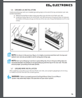
Here's the manual page about grounding the rack:
View attachment 225437
It's quite a bit of overkill. But Larger is fine, the required size is a minimum requirement.Although it might seem silly, my new install with 4x 10A PV strings wired 12 awg will have 4 awg ground wire.
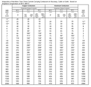
That table is for current carrying conductors, not EGC's.I would say do not use this table for ground conductors of PV, which don't trip breakers.
Continuous current, so use this one:
I would ground (bond) PV frames to the DC side, at the SCC or inverter.
Not directly to the AC breaker panel or ground rod, because I don't want DC current from a fault going there first, then going back through AC ground wire to reach SCC. If an electrician disconnected the AC circuit (with power off) he would be surprised when it pulled a DC arc.
Yes. Connect at DC hardware, I say.
Exactly.
If there is a PV DC fault to frame, the ground bonding wire carrying fault current should be routed together with the PV wires, completing a circuit without having a big loop or going through the wires of some other circuit.
At the array, often single wires so those have space between them.
If routed to avoid that, might be better at avoiding pickup of RF interference and coupled lightning surge.
And use wire to stitch everything together. Don't use chassis as part of the ground path for faults to any other hardware, only for faults to that chassis.
Exception being when PV mounting rails are used as ground conductors.
Yes. Required according to my understanding of NEC.
And this means bond the wire at SCC or inverter chassis. Not at AC breaker panel or at ground rod.
Lay-in lugs. Lets you remove and unhook a panel without interrupting ground wire to rest of them.
Alternatively, some panel clamps, also WEEB washers, provide bonding of panel frame to rails.
Looking through SolarAPP+ I discovered REC panels were listed for bonding with Unirac clamps, but NE Solar were not.
Although it might seem silly, my new install with 4x 10A PV strings wired 12 awg will have 4 awg ground wire.
In part because I have it (from 200A service upgrade, where 6 awg would be sufficient except code requires 4 awg to water pipe.) But also:
Consider 10A Isc x 1.56 x 4 parallel strings all shorted = 62.4 A ampacity required for continuous use.
I would say do not use this table for ground conductors of PV, which don't trip breakers.
Continuous current, so use this one:
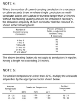
I could have 4x PV+ + 1x Ground carrying current, so derate to 80%.
Looks like 4 awg is just about right.


