Bluedog225
Texas
Solar charge controller. We love our acronyms.
Are we allowed to use coated 10awg copper for panel frames and such, just running from panel to panel with no protective conduit? It doesn't need to be fat 6awg aluminum or something?
If exposed to physical damage (Not in conduit), the minimum size required is #6.
And yes green insulated stranded copper, is what I use and recommend.
Usually the easiest solution is to run the appropriate size in conduit to a box (combiner, junction, or pull box). Then connect it to a #6 , that runs exposed behind the panels.What counts as not in conduit? If you had conduit behind your ground mounted solar panels, right up against the frame of the panel, to keep critters and such from having as much cable to chew on, and had your EGC in there, and it was only 10awg..
Could you expose it briefly, say a few inches, to connect to a ground lug on the panel / racking?
Or is that too much distance not in conduit and you need to use 6awg and then downgrade it back to 10awg for the run in conduit?
It's quite a bit of overkill. But Larger is fine, the required size is a minimum requirement.
That table is for current carrying conductors, not EGC's.
Current carrying conductors have to be rated for full current continuously without overheating.
EGC's are only rated for instantaneous fault current, which only lasts for a second.
This is why they can be much smaller.
Thanks for all the useful info, what does SCC stand for though?
And thanks everyone, super helpful info here!
What counts as not in conduit? If you had conduit behind your ground mounted solar panels, right up against the frame of the panel, to keep critters and such from having as much cable to chew on, and had your EGC in there, and it was only 10awg..
Could you expose it briefly, say a few inches, to connect to a ground lug on the panel / racking?
Or is that too much distance not in conduit and you need to use 6awg and then downgrade it back to 10awg for the run in conduit?
Scc solar charge controllerThanks for all the useful info, what does SCC stand for though?
And thanks everyone, super helpful info here!
EGC is for protection against shock from the AC power.That would be the case if they could trip a breaker, which is the case for AC circuits and battery circuits.
I say that EGCs for PV DC are current-carrying conductors.
I have never seen issues with copper to steel (it's usually coated or painted) , but aluminum, and tin should be avoided. Galvanized coating should provide a good barrier.Tim - what dissimilar contact should I avoid? Just bare copper to aluminum? How about bare copper to galvanized steel? How about bare copper to bare steel? I've made holes in electrical boxes and run bare ground wire out through it.
Thank you for your patience, learning something new today. So I run a wire through an EGC lug on each of the panel frames, all the way back to my N+G bonded busbar at service entry in the same conduit as my PV wires? It's over 100ft away so not sure if that's an issue.No, they are not already grounded.
You have to run an EGC (Equipment Grounding Conductor) from the panel frames and racking back to the grounding system to ground/ Bond them.
Which is what I thought that you had done, when you said that they were grounded by extension from the inverter.
If that is where your Solar Charge Controller is as well. Ground it to your buildings grounding system near the location your PV wires were going to go into your SCC.Thank you for your patience, learning something new today. So I run a wire through an EGC lug on each of the panel frames, all the way back to my N+G bonded busbar at service entry in the same conduit as my PV wires?
It is not.It's over 100ft away so not sure if that's an issue.
If you aren't sure your rack is grounded by touching the panels (which you are grounding), then ground the rack as well. It can use the same wire as the panels are using.Then after that, I don't need to ground the rack itself?
Yes, it's an MPP Solar LV6548 inverter, the AC output ground is attached there as well, it's the point of ground for everything both on grid and off grid.If that is where your Solar Charge Controller is as well. Ground it to your buildings grounding system near the location your PV wires were going to go into your SCC.
It is not.
If you aren't sure your rack is grounded by touching the panels (which you are grounding), then ground the rack as well. It can use the same wire as the panels are using.
All metal attached to your system, ground it.
Back to any part of the grounding system.Thank you for your patience, learning something new today. So I run a wire through an EGC lug on each of the panel frames, all the way back to my N+G bonded busbar at service entry in the same conduit as my PV wires? It's over 100ft away so not sure if that's an issue.
The rack also needs to be grounded.Then after that, I don't need to ground the rack itself?
EXACTLY. Maybe timselectric can read this and comprehend it.I love this thread. It's got a lot of good info.
There is "earth ground" and "equipment ground"
For equipment ground there is AC ground and DC ground.
If there is a grid connection at the property, then the utility provides at the service entrance for normal 240V residencies (in USA) an L1 black hot 120 volts, an L2 red hot 120 volts which are out of phase with each other (ie split phase), a neutral (white which completes the circuit) and a bare copper or insulated green copper wire which is the AC ground. There is a required BOND at only one point in the main panel between the neutral wire and the utility ground wire. This is the only place anywhere on the AC side that a neutral to ground connection should exist. Arising from this BOND is the ground buss bar and neutral buss bar. The purpose of the neutral wire is to complete the circuits to operate equipment such as a blender. The purpose of the ground wire is to connect to equipment chassis such as a microwave oven exterior, an electric fan case, a metal mounting box, etc. By grounding these metallic equipment fixtures, there is a route for current to flow if the neutral is interrupted (rather than only through a body) and this helps prevent shocks and electrocution.
On the DC side, earth ground is accomplished by either making certain a bonded connection of a copper wire to a solar panel frame and any metallic parts of the PV mount are connected to a ground rod locally or carried back via a bare copper wire or insulated copper wire to an accessible AC grounding buss bar point or grounding rod. The solar array carries current under normal conditions by means of two conductors, PV+ and PV- to make a DC circuit that lands on a PV charge controller or other DC capable appliance. Without any grounding of the array, panels or the landing equipment, a person could be electrocuted by DC current passing through their body if they come in contact with a live DC circuit.
If a PV array has a locally installed (at the array) combiner box and DC disconnect, and if they are metallic, they must be grounded via a wire connection. Use of PVC boxes and conduits outdoor carrying DC circuits should also carry a grounding wire inside them unless the PV array is earth grounded at the array. If the PV array is earth grounded at the array, and no ground wire travels to the landing equipment of the DC circuit, then that landing equipment must be grounded locally by either a grounding rod or to the AC ground buss point.
If off grid, this can be by a grounding rod and ground buss bar and wires between batteries, inverter, charge controllers, sub panels, conduits (metallic indoors) and any other electrical equipment and metallic boxes. In an off grid case, with an inverter and AC power, a ground to neutral BOND is created in only one location, usually at the inverter. If you are off grid and using a portable generator tied into your off grid inverter, the neutral to ground BOND is again, only in the inverter, not at the generator. If using a portable generator in a free standing condition not connected to an inverter, then that generator should have an internal neutral to ground bond and even a grounding rod connection.
Now, if the DC circuit is brought to a landing where there is a utility grid tie, then the grid tie will supply an AC side ground that originated in the main panel service entrance. In this case, your DC ground from the array carried by the ground wire can land on the AC buss bar to establish equipment ground and earth ground. There would be no neutral to ground bond at the inverter or a generator. And there would be no grounding rod at the array.
I think you need to read this again.EXACTLY. Maybe timselectric can read this and comprehend it.
NEC does allow for a ground rod at a PV array, but it REQUIRES that and any metallic components exposed to be tied to the home main grounding conductor...
NoAre there certain extreme distances where it makes sense?
NoneWhat is the potential benefit?
Why put in an ancillary grounding rod? It just seems like extra work for nothing to me.
Are there certain extreme distances where it makes sense?
What is the potential benefit?
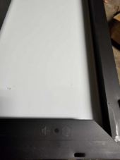
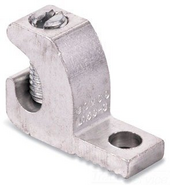
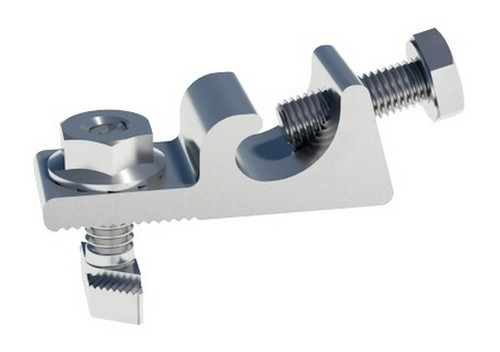
Your lug shown is to lay the copper ground wire in the inlay and tighten it down with the screw. HOWEVER, THAT PARTICUALR LUG IS CHEAP AND REQUIRES A SCREW AND NUT WHICH WILL MAKE THE BOND BETWEEN THE FRAME AND THE LUG. THIS IS USUALLY A GROUNDING NUT OR GROUNDING SCREW WITH I THINK AT LEAST THREE THREAD TURNS THROUGH THE PANEL FRAME.Thank you for your patience, learning something new today. So I run a wire through an EGC lug on each of the panel frames, all the way back to my N+G bonded busbar at service entry in the same conduit as my PV wires? It's over 100ft away so not sure if that's an issue.
Then after that, I don't need to ground the rack itself?
View attachment 225469
View attachment 225470
I think the issue is that you rubber stamped a pretty long post that was about 90% accurate but had some details that were off either due to fundamental inaccuracy or poor word choice (I read the grounding system and at least a skim could make it sound like a TN-S instead of TN-C-S. And that’s not good)Sure, ignore me. I only have 44 years in the industry engineering large diesel generators and 50 mw battery systems at over 6,000 sites across the US. I also happen to hold an electrical contractor's license in two states. Have fun with your forum.
Do you have any examples of correct bonding screw to be used here, or a better alternative product?Your lug shown is to lay the copper ground wire in the inlay and tighten it down with the screw. HOWEVER, THAT PARTICUALR LUG IS CHEAP AND REQUIRES A SCREW AND NUT WHICH WILL MAKE THE BOND BETWEEN THE FRAME AND THE LUG. THIS IS USUALLY A GROUNDING NUT OR GROUNDING SCREW WITH I THINK AT LEAST THREE THREAD TURNS THROUGH THE PANEL FRAME.
Just tightening this lug to the frame will not bond the lug to the frame. the proper screw and screw/nut to make the bond must be used.
There are more expensive lugs that make the bond when tightened to the frame.
 www.stellavolta.com

