diy solar

diy solar

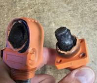
Beware of the APEXIUM BOX Connectors

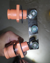
My factory-assembled Apexium 280A box with cables.

I suspect the mating between the plug and socket is electrically poor and not substantial enough for the loads it is meant to carry. At least in my unit it always felt like the plug connected to the socket easily with hardly any mechanical force required. My theory might be incorrect but I am not going to continue with these imitation connectors, I am replacing them with screw-down posts to which I can bolt down a ring lug.

These are not Futronics connectors. I bought Futronics from Minerals on AliExpress and although the Futronics does fit the socket they do not "click" in place and feel loose. They do not have any markings on them other than "200A 50mm".

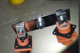
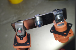
I will rectify the busbar connecting the + terminals. As pointed out in another thread, it seems to have been incorrectly assembled and that could also have lead to heat in the cable - note the discoloured label.
Op had bad crimp on one end and what appears be bus bar - washer sandwich other end ….heat meeting in middle of probable loose - improper applied snap push on cable connector. Op was only concerned with documentation after the fact not before.
OP had futronic connectors on his own personal battery so knew the diff.

Bolt on connections especially with customers is a good idea. They have to use tools to mess with it. We called that use of tools child proofing years ago.
 
My factory-assembled Apexium 280A box with cables.

I suspect the mating between the plug and socket is electrically poor and not substantial enough for the loads it is meant to carry. At least in my unit it always felt like the plug connected to the socket easily with hardly any mechanical force required. My theory might be incorrect but I am not going to continue with these imitation connectors, I am replacing them with screw-down posts to which I can bolt down a ring lug.

These are not Futronics connectors. I bought Futronics from Minerals on AliExpress and although the Futronics does fit the socket they do not "click" in place and feel loose. They do not have any markings on them other than "200A 50mm".

I will rectify the busbar connecting the + terminals. As pointed out in another thread, it seems to have been incorrectly assembled and that could also have lead to heat in the cable - note the discoloured label.
Wow, that looks awful!
 
I lied: Similar, but not the same. Kinda hope it's not inter-matable!

The Degson 250A connectors will rotate after insertion. Also, if you use enough force and the proper twisting motion you can uncouple the latch and remove the connector without resorting to the button (by damaging the tiny little latch piece, barely visible in the second picture. Just plug them in forcefully till they snap and leave them alone.

FWIW: That's an M8-12.25 thread on the panel mount connector tab.View attachment 223115View attachment 223116
Also, it turns out that the (hundred amp?) connectors on the ChargeVerter GC are not Degson. They get warm (not hot) as do the connecting cables supplied with the ChargeVerter, but nothing has melted yet. also, unlike the Degson connectors on the batteries, you can plug positive into negative and vice versa.
 
Also, it turns out that the (hundred amp?) connectors on the ChargeVerter GC are not Degson. They get warm (not hot) as do the connecting cables supplied with the ChargeVerter, but nothing has melted yet. also, unlike the Degson connectors on the batteries, you can plug positive into negative and vice versa.
That would be bad …. Those connectors are on charge inverter? Got any pictures? Thanks
 
The key point of that thread is the person used a stainless steel washer in the path of the current flow. Current flows from the battery pad to the lug face, not throught the threaded part.

In his case he had washer - fuse - washer - lug - washer - nut ... all stainless steel which will get hot because it isn't a good conductor.

So long as it isn't in the path of current flow you can use a steel washer as a spacer. If it is in the path of current flow you can use a pure copper washer that has been cleaned at it will act as a bus bar.
That is completely wrong, the was no washer between the bussbar and lug. You people are just making things up.
 
Op had bad crimp on one end and what appears be bus bar - washer sandwich other end ….heat meeting in middle of probable loose - improper applied snap push on cable connector. Op was only concerned with documentation after the fact not before.
OP had futronic connectors on his own personal battery so knew the diff.

Bolt on connections especially with customers is a good idea. They have to use tools to mess with it. We called that use of tools child proofing years ago.
Again you are manufacturing facts, the crimp was not bad and there was no washer. It was a bad connector. The connector was faulty. So everyone should take precautions. This is one example of the damage that can result. So stop making things up and listen to the warning.
 
No, That is not a washer it is damaged metal from the heat, again this is a precautionary post. Don't make s stuff up to minimize the damage that can be done from a bad connector.
I get what you are saying, but why is that melted connector on an angle from the busbar? Is that something that happened during disassembly?

Yeah, everyone, myself included, is off on the "connector to busbar" tangent, when the clear primary source of the heat is the poor connectivity at the plug-in connector. You're not wrong, we're just trying to tease out all the available information to determine root cause, secondary causes and follow-on events, and best practices for prevention going forwards.
 
No, That is not a washer it is damaged metal from the heat, again this is a precautionary post. Don't make s stuff up to minimize the damage that can be done from a bad connector.
Kinda defensive?

What is the round thing at the bottom? Photos were asked for, none provided.

I would not use this type of connector but some may already have a battery with this type. In the interest of safety, all possible scenarios are presented to determine what is the cause of failure. If you want to dismiss a theory, then you have to be willing to back it up. I have not seen any evidence concerning washers, bad crimps or other possible failure points that will disprove those possibilities.
 
  • Like
Reactions: D71
I thought there were going to be photos of the connector crimp when it was cut open to prove or dispel a bad crimp/cold weld?

Did I miss them?

Either way I’m staying away from these types of connectors. IMO they are the duplex backstab of battery terminals.
 
I thought there were going to be photos of the connector crimp when it was cut open to prove or dispel a bad crimp/cold weld?

Did I miss them?

Either way I’m staying away from these types of connectors. IMO they are the duplex backstab of battery ter

Kinda defensive?

What is the round thing at the bottom? Photos were asked for, none provided.

I would not use this type of connector but some may already have a battery with this type. In the interest of safety, all possible scenarios are presented to determine what is the cause of failure. If you want to dismiss a theory, then you have to be willing to back it up. I have not seen any evidence concerning washers, bad crimps or other possible failure points that will disprove those possibilities.
I guess it adds significant value to the conversation to mention that using washers is not good and bad crimps are also a potential point of failure.

So please exhaust all possible scenarios of a potential failure.

If it provides some knowledge and can help prevent a catastrophic disaster. Fair enough!!
 
I get what you are saying, but why is that melted connector on an angle from the busbar? Is that something that happened during disassembly?

Yeah, everyone, myself included, is off on the "connector to busbar" tangent, when the clear primary source of the heat is the poor connectivity at the plug-in connector. You're not wrong, we're just trying to tease out all the available information to determine root cause, secondary causes and follow-on events, and best practices for prevention going forwards.
It is obvious that the bussbar and connectors were disassembled from the battery pack because there are no pictures of the battery pack. Everybody should have realized that because where is the battery pack in the picture?
 
My factory-assembled Apexium 280A box with cables.

I suspect the mating between the plug and socket is electrically poor and not substantial enough for the loads it is meant to carry. At least in my unit it always felt like the plug connected to the socket easily with hardly any mechanical force required. My theory might be incorrect but I am not going to continue with these imitation connectors, I am replacing them with screw-down posts to which I can bolt down a ring lug.

These are not Futronics connectors. I bought Futronics from Minerals on AliExpress and although the Futronics does fit the socket they do not "click" in place and feel loose. They do not have any markings on them other than "200A 50mm".

I will rectify the busbar connecting the + terminals. As pointed out in another thread, it seems to have been incorrectly assembled and that could also have lead to heat in the cable - note the discoloured label.
It looks like you had the same problem I had.
 
Only thing I'll add, not in his defense but just to correct others.
The washer we thought we saw was in fact just light passing through the threaded hole, the blown up photo actually made it more unclear.
 
Last edited:
  • Like
Reactions: D71
Only thing I'll add, not in his defense but just to correct others.
The washer we thought we saw was in fact just light passing through the threaded hole, the blown up photo actually made it more unclear.
The optical illusion strikes again. :)
 
Only thing I'll add, not in his defense but just to correct others.
The washer we thought we saw was in fact just light passing through the threaded hole, the blown up photo actually made it more unclear.
That is hilarious that you have to validate your observation. I have said from the get go that there was no washer there. But the trolls will troll! Furthermore another owner has had a similar occurrence. Everyone beware that these connectors could potentially have an issue that could result in a failure.

1719803856536.png
1719803914306.png1719803996861.png
 
Only pointing out that there's no washers between the busbar there's plenty of other things have been mentioned, though personally I would have added some spring washers to the rear between the bolt head and the bus bar. From the above photo it shows some annealing between the connector and busbar, we still can't be sure the connector was totally at fault( yes we know they are underpriced copies).
Not sure from the photo but the connectors connection to the busbar looks like its been sanded, even if you aren't at fault it makes you seem far more suspicious if original damage and burn patterns have been erased especially when others want to investigate.
 
That is hilarious that you have to validate your observation. I have said from the get go that there was no washer there. But the trolls will troll! Furthermore another owner has had a similar occurrence. Everyone beware that these connectors could potentially have an issue that could result in a failure.

View attachment 225747
View attachment 225748View attachment 225749


So, here is a theory - is it possible the no-name connectors have a max current of say 200amps and by hooking up 6 batteries in parallel you allowed that max to be exceeded?
 
Only pointing out that there's no washers between the busbar there's plenty of other things have been mentioned, though personally I would have added some spring washers to the rear between the bolt head and the bus bar. From the above photo it shows some annealing between the connector and busbar, we still can't be sure the connector was totally at fault( yes we know they are underpriced copies).
Not sure from the photo but the connectors connection to the busbar looks like its been sanded, even if you aren't at fault it makes you seem far more suspicious if original damage and burn patterns have been erased especially when others want to investigate.
That is the bottom of the bussbar. I figure that most people realize there is a top and bottom view. I guess you don't know anything about these batteries because there is a lock washer between the bolt and flat washer. These are the original unaltered photos below. Anybody who is reading this thread please disregard all the nonsensical conjecture and realize the potential hazards that can happen.
1719808949437.png
1719808982506.png
 
Last edited:
So, here is a theory - is it possible the no-name connectors have a max current of say 200amps and by hooking up 6 batteries in parallel you allowed that max to be exceeded?
That is not how the system works! You cant exceed the maximum output and input amperage set in your inverter settings. Unless there is a problem!!! In this case there were only 3 batteries in parallel. For this particular setup it was set at 0.20c discharge and charge amperage or max 160Amps. A great feature of the computer based monitoring system is a BMS history log. After anylizing the BMS's histories, the maximum charging/discharging amperage was 47amps from any one battery, so times that by 3 batteries in parallel it was 140 amps charging current coming from the MPPT or being discharged to the inverter.

Thanks for the theory though, it's been very helpful hearing all the input. It has helped eliminate many potential causes. Much appreciated everyone!
 
Last edited:
Do you have this defect connector in your possession now or are the pictures still coming from professional solar installer.?

Got the dead on pictures of both mating surfaces for bus bar and connector mating surfaces like was asked for on 18 June 2024?

You offered to sell some of those connectors that you are calling defect?

What are you going to do with the so-called bad connectors from the 30 apexium diy boxes that you bought? Why did you edit out the 30 boxes?

Are you going to upgrade and change out all the connectors you identified as defective?

Did you talk to professional solar installer about the less than quality crimp the kind you agreed about wasn’t so good?
 
That is the bottom of the bussbar. I figure that most people realize there is a top and bottom view. I guess you don't know anything about these batteries because there is a lock washer between the bolt and flat washer. These are the original unaltered photos below. Anybody who is reading this thread please disregard all the nonsensical conjecture and realize the potential hazards that can happen.
View attachment 225753
View attachment 225754
Your right I know nothing of these connectors, I use a lug and busbar/terminal for all high amperage connections, though it doesn't stop the decades of experience I have in manufacturing engineering from being inquisitive. You only needed to add that there was infact a spring washer which doesn't seem to have made the contact any better hence the burning between where the connection and busbar meet. It's obvious that there was excessive heat in the poor quality quick connect you used, I'm just trying to ascertain whether that was the primary point of failure or the secondary.

Metals expand when heated which will obviously cause this type of connector to fail, but was the heat from the quick connect the primary source or some other source IE the busbar or a crimp that caused the connect to be a secondary failure point.

You can't expect to post a thread such as this on a forum filled with keen DIYers and a vast array of engineers (likely a troll or two also) and expect us not query you or come up with our own conclusions.
 
  • Like
Reactions: D71
Your right I know nothing of these connectors, I use a lug and busbar/terminal for all high amperage connections, though it doesn't stop the decades of experience I have in manufacturing engineering from being inquisitive. You only needed to add that there was infact a spring washer which doesn't seem to have made the contact any better hence the burning between where the connection and busbar meet. It's obvious that there was excessive heat in the poor quality quick connect you used, I'm just trying to ascertain whether that was the primary point of failure or the secondary.

Metals expand when heated which will obviously cause this type of connector to fail, but was the heat from the quick connect the primary source or some other source IE the busbar or a crimp that caused the connect to be a secondary failure point.

You can't expect to post a thread such as this on a forum filled with keen DIYers and a vast array of engineers (likely a troll or two also) and expect us not query you or come up with our own conclusions.
I have thanked and acknowledged the great amount of input in this thread, if one person gets value from any of this. A good service has been done.

Thaidaffy You blatantly implied that I was acting suspect which of course distracts people from helpful facts.
 
Last edited:

diy solar

diy solar
Back
Top