So far what I've learned is I can wire it up direct to a mains 30 amp rated fuse on the distribution board like the cooker fuse,3.6kW has its advantages in the UK. Under code G98 you don't need to apply for permission to connect it to the grid, you only need to notify the network company within 14 days of commissioning. Over 3.6kW comes under code G99 and you need to get permission in advance.
Of course you still have to make sure all the relevant electrical codes are followed.


You are using an out of date browser. It may not display this or other websites correctly.
You should upgrade or use an alternative browser.
You should upgrade or use an alternative browser.
Am i buying a decent hybrid and is it legitimate advice needed,
- Thread starter heather-
- Start date
Ampster
Renewable Energy Hobbyist
To clarify, do you mean the same fuse as the cooker or one similar to the cooker fuse? It should definitely be on its own dedicated fuse or breaker.So far what I've learned is I can wire it up direct to a mains 30 amp rated fuse on the distribution board like the cooker fuse,
Understood, as I'm understanding it between the grid connection port, the AC, on the inverter and before the mains I need to put a 16 amp circuit breaker and a 16 amp rotary switch isolator.To clarify, do you mean the same fuse as the cooker or one similar to the cooker fuse? It should definitely be on its own dedicated fuse or breaker.
Then when wiring it into the mains distribution fuse board put it on it's own 30 amp rated MCB breaker.
Then I need to connect the load up, where do I connect the load from the inverter to thanks

Last edited:
It looks like the specified circuit breaker is 40 amps between the inverter grid and the mains distribution board, would that be right, and why is that when the grid only outputs 16 Amps, I'm a bit puzzled.Understood, as I'm understanding it between the grid connection port, the AC, on the inverter and before the mains I need to put a 16 amp circuit breaker and a 16 amp rotary switch isolator.
Then when wiring it into the mains distribution fuse board put it on it's own 30 amp rated MCB breaker.
Then I need to connect the load up, where do I connect the load from the inverter to thanks
Also why should I add a rotary isolator on the same line too between the grid connection on the inverter and the mains distribution board, after the circuit breaker and before the 30 amp MCB trip switch in the mains distribution board.
Also for extending the solar panel cable by 30 meters, what thickness of wire would anyone recommend.
On a load of 2400 watts from the panels, this inverter has two built in mppt charge controllers, so I'm splitting my 8 panels on two separate strings as 6 are the same, which are the Trina 415 pannels, and two panels are longi 420 panels.
My plan is to put the Longi panels on the second string on the inverter, as there a slightly different amp and voltage to the Trina panels.
Would I be ok to couple to an existing wire that is already there, it's a twin earth type wire of 25 mm,
Or would I be better of putting a thicker wire, which then means me having to go under the floor boards, which I could do without but I will have to if recommended.
On the sunsynk inverter there is a built in isolator for the solar panel inputs, but would it still be advisable to add a circuit breaker on the solar panel wire before the built in solar panel isolator,.thanks

Also would this battery be ok for a sunsynk 3.6k inverter, which I can get brand new for 600
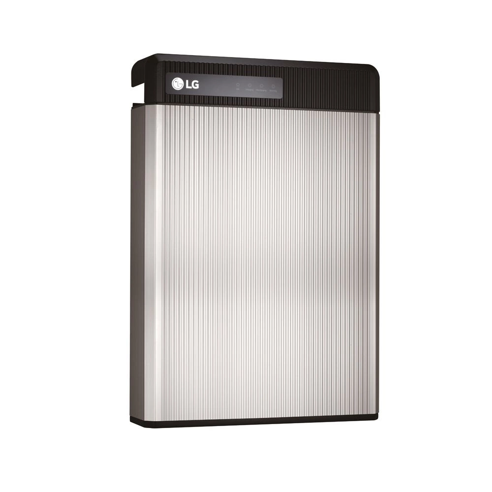
Battery Energy Storage LG CHEM RESU 6.5 - 48V 6.5KWH
Compatibility: Sungrow SH3-4K6, Sungrow SH5K-20/30, SolarEdge SE5-10K RWS, Sunny Island 3-4M, Sunny Island 6H
Last edited:
OK... I understand the OP has long since blocked me because they didn't like my safety comments earlier in this thread. But I am adding my feedback here for anyone else from the UK who happens to read this thread in the future...
1) Any electrical work (and this is not specific to solar) work has to be done to BS7671 IET standards by a "competent" or "skilled" person. To quote from the IET this refers to "a person who possesses, as appropriate to the nature of the electrical work to be undertaken, adequate education, training and practical skills, and who is able to perceive risks and avoid hazards which electricity can create.’ They are different terms, but they all mean the same thing, the person carrying out the inspection and testing is required to have the correct qualifications, experience and knowledge." However, in practice, as long as the DIY stores keep selling wire and sockets, there will unfortunately always be people doing DIY electrical work on their houses without those necessary skills.
2) Any electrical work (again, not specific to solar) must be building regulations part P compliant. This is government legislation to cover electrical safety in dwellings to minimise risk of shock or fire. Part P compliance can be achieved with DIY if you pay local authority and get building control involved (and obviously do the work to the required standard), but as that is costly and time-consuming it is usually better to get a sparky in who is Part P certified to do the work for you - in that case they will sign off the work on your behalf.
Not all electrical work is notifiable under Part P, but a) adding any new circuit, b) 'modifying-or-adding to a circuit in a notifiable location' (e.g. a room with a bath or shower) and c) replacement of a consumer unit (= UK term for main fuse or distribution box) is notifiable work.
IMHO, these questions below from the OP, together with the shocking pictures of the installation, suggest the OP is not a competent or skilled person with regard to BS7671 and the work that is required comes under the legislation of Building Regulations Part-P. (& that's the polite version of my thoughts).
No, not legally, as I have pointed out several times earlier.So far what I've learned is I can wire it up direct to a mains 30 amp rated fuse on the distribution board like the cooker fuse,
1) Any electrical work (and this is not specific to solar) work has to be done to BS7671 IET standards by a "competent" or "skilled" person. To quote from the IET this refers to "a person who possesses, as appropriate to the nature of the electrical work to be undertaken, adequate education, training and practical skills, and who is able to perceive risks and avoid hazards which electricity can create.’ They are different terms, but they all mean the same thing, the person carrying out the inspection and testing is required to have the correct qualifications, experience and knowledge." However, in practice, as long as the DIY stores keep selling wire and sockets, there will unfortunately always be people doing DIY electrical work on their houses without those necessary skills.
2) Any electrical work (again, not specific to solar) must be building regulations part P compliant. This is government legislation to cover electrical safety in dwellings to minimise risk of shock or fire. Part P compliance can be achieved with DIY if you pay local authority and get building control involved (and obviously do the work to the required standard), but as that is costly and time-consuming it is usually better to get a sparky in who is Part P certified to do the work for you - in that case they will sign off the work on your behalf.
Not all electrical work is notifiable under Part P, but a) adding any new circuit, b) 'modifying-or-adding to a circuit in a notifiable location' (e.g. a room with a bath or shower) and c) replacement of a consumer unit (= UK term for main fuse or distribution box) is notifiable work.
IMHO, these questions below from the OP, together with the shocking pictures of the installation, suggest the OP is not a competent or skilled person with regard to BS7671 and the work that is required comes under the legislation of Building Regulations Part-P. (& that's the polite version of my thoughts).
where do I connect the load from the inverter to thanks
I'm a bit puzzled.
Also why should I add a rotary isolator on the same line too between the grid connection on the inverter and the mains distribution board,
Also for extending the solar panel cable by 30 meters, what thickness of wire would anyone recommend.
Would I be ok to couple to an existing wire that is already there, it's a twin earth type wire of 25 mm
Will the two panels put out enough voltage to work with the inverter? I've not looked up the spec of that inverter and those panels, but typical panel output is around 40V each and the inverter's MPPT voltage range often starts higher than 2x that.On a load of 2400 watts from the panels, this inverter has two built in mppt charge controllers, so I'm splitting my 8 panels on two separate strings as 6 are the same, which are the Trina 415 pannels, and two panels are longi 420 panels.
My plan is to put the Longi panels on the second string on the inverter, as there a slightly different amp and voltage to the Trina panels.
You can get away with mixing and matching panels in a single string, but the current will be limited to that of the lowest rated panel.
Check the specifications to see what the inverter can handle and what the panels can output.
Thanks will the inverter work for now if I connect 6 panels on one string and leave the other string empty.Will the two panels put out enough voltage to work with the inverter? I've not looked up the spec of that inverter and those panels, but typical panel output is around 40V each and the inverter's MPPT voltage range often starts higher than 2x that.
You can get away with mixing and matching panels in a single string, but the current will be limited to that of the lowest rated panel.
Check the specifications to see what the inverter can handle and what the panels can output.
Untill I make my mind up, it just I'm getting strange readings when I mix and match the panels. I'm getting the inverter shortly
I'm not sure, but is it the case each mppt charge controller needs a 120 volt start up ?.Will the two panels put out enough voltage to work with the inverter? I've not looked up the spec of that inverter and those panels, but typical panel output is around 40V each and the inverter's MPPT voltage range often starts higher than 2x that.
You can get away with mixing and matching panels in a single string, but the current will be limited to that of the lowest rated panel.
Check the specifications to see what the inverter can handle and what the panels can output.
Quattrohead
Solar Wizard
I am probably blocked too but if I was the OP I would be double checking that that LG cam battery is not one of the faulty ones that really can catch fire.
Getting cheap products from builders mates etc sounds like a sure way of getting ripped off or receiving stolen goods LOL
Getting cheap products from builders mates etc sounds like a sure way of getting ripped off or receiving stolen goods LOL
Hence the £600 that's half the price I can get a similar spec battery here in cheepo landI am probably blocked too but if I was the OP I would be double checking that that LG cam battery is not one of the faulty ones that really can catch fire.
Getting cheap products from builders mates etc sounds like a sure way of getting ripped off or receiving stolen goods LOL
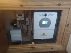
My new inverter has arrived 
Fits nicely in my cupboard to.
I'm in the process of now wiring it up chuckles.
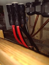
From the picture which wire would I put the magnet ct coil to measure current going back to the grid and which way would i point the arrow on the magnet , in the direction of flow towards meter or in the direction of flow towards the inverter,
Please also advice best, with isolator rotary switch and circuit breaker between the inverter grid connection and distribution board, as in amp ratings too, thanks
This is the 3.6k version
Fits nicely in my cupboard to.
I'm in the process of now wiring it up chuckles.
From the picture which wire would I put the magnet ct coil to measure current going back to the grid and which way would i point the arrow on the magnet , in the direction of flow towards meter or in the direction of flow towards the inverter,
Please also advice best, with isolator rotary switch and circuit breaker between the inverter grid connection and distribution board, as in amp ratings too, thanks
This is the 3.6k version
Attachments
Last edited:

Best read the instructions especially the part about the inverter mounting, see below;From the picture which wire would I put the magnet ct coil to measure current going back to the grid and which way would i point the arrow on the magnet , in the direction of flow towards meter or in the direction of flow towards the inverter,

Ooh, that'll keep it nice and warm.My new inverter has arrived
Fits nicely in my cupboard to.

What do you mean ?Ooh, that'll keep it nice and warm.
Its
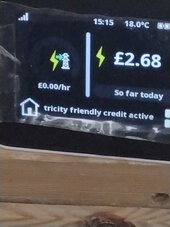
Well at the time luckily it was cloudy and my solar array was only pulling 690 watts, I checked my smart meter and it showed up as 1 p per hour instead of 20p per hour,
This must show I've set it up correctly,.
On my smart meter now I have the strange picture of an electric tower come up on my display next to lightening bolt symbol,
It was not there befor,
As you can see on my smart meter I'm being charged 0 pence per kWh with currently using electric appliances at my house.
Also what does trickle friendly credit active mean ?
It's up and running now I've just had my TV on fridge freezer on and my hover on, which consumes about total 700 watts per hour, which would normally show up as 20p per hour on my smart meter,Ooh, that'll keep it nice and warm.
Well at the time luckily it was cloudy and my solar array was only pulling 690 watts, I checked my smart meter and it showed up as 1 p per hour instead of 20p per hour,
This must show I've set it up correctly,.
On my smart meter now I have the strange picture of an electric tower come up on my display next to lightening bolt
symbol,It was not there befor,
As you can see on my smart meter I'm being charged 0 pence per kWh with currently using electric appliances at my house.
Also what does trickle friendly credit active mean ?
Attachments
Last edited:
I must be doing something wrong cause my electric has cost about $20k in the last 2 years. It's expensive being your own power company. Lets not even get into the cost of being your own water company....lolhi, hope your all well, and enjoying free electric, chuckles.
I've just boiled a full 2 kWh kettle of water at zero pence and hour on my smart meter , chuckles.I must be doing something wrong cause my electric has cost about $20k in the last 2 years. It's expensive being your own power company. Lets not even get into the cost of being your own water company....lol
I take it thats all the equipment you've bought to set up ?,I must be doing something wrong cause my electric has cost about $20k in the last 2 years. It's expensive being your own power company. Lets not even get into the cost of being your own water company....lol
My total set up fee is about only no more than 1400 UK pounds, it should have been more like close to 3000 , but I managed to source, some good deals
Which I'll get back within about 12 months if I charge my EV, for my miles I use.
I take it with 20k setup like yours, your consuming a lot of electricity
Do I need to be concerned about anything here.
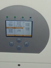
On one string I have a mixed brand solar array of two Longi 420 watt panels and two Trina 415 watt panels,
And on the other string I have 4 X Trina 415 watt panels,
As you can see from the picture I'm getting different power coming in.
There is more shading on one array at the moment, but even in clear sunlight, there is always about a 50 to 60 watt difference
Attachments

Last edited:
Ok thanks, sorry for the upside down pic, you should be able to rotate it, with a photo app.Post the specs for each panel.
"Watts" doesn't tell us how well they will mix in series, or in parallel.
Volts and Amps would.
or turn your phone side ways xAttachments
Last edited:
Hedges
I See Electromagnetic Fields!
- Joined
- Mar 28, 2020
- Messages
- 21,837
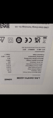
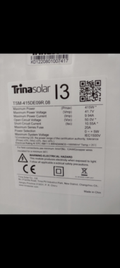
Trina 415W | |
41.7 | Vmp |
9.94 | Imp |
| |
Longi 420W | |
31.37 | Vmp |
13.24 | Imp |
Trina current is 75% of Longi current.
Connected in series you lose 25% of Longi power output.
Longi voltage is 75% of Trina voltage.
You have two strings, one 4s Trina, the other 2s Trina + 2s Longi.
Are these two string connected each to a separate MPPT input?
Or are they paralleled into a single input, something similar to 4s2p (except one of the 4s isn't homogenous) ?
I'd rather see 2s Longi on one MPPT, 2s3p Trina on a second MPPT (or spread over additional MPPT.
That's if 62 Vmp, lower on hot days, is sufficient for your system.
But if you need the voltage of 4s, what you've got will still work. Avoid shading of the Longi! Excessive current forced through bypass diode when Trina in full sun would damage it!
Hi the sunsynk inverter has two mppt controller built in, each one can handle 3600 watt input I think.
Trina current is 75% of Longi current.
Connected in series you lose 25% of Longi power output.
Longi voltage is 75% of Trina voltage.
You have two strings, one 4s Trina, the other 2s Trina + 2s Longi.
Are these two string connected each to a separate MPPT input?
Or are they paralleled into a single input, something similar to 4s2p (except one of the 4s isn't homogenous) ?
I'd rather see 2s Longi on one MPPT, 2s3p Trina on a second MPPT (or spread over additional MPPT.
That's if 62 Vmp, lower on hot days, is sufficient for your system.
But if you need the voltage of 4s, what you've got will still work. Avoid shading of the Longi! Excessive current forced through bypass diode when Trina in full sun would damage it!
So Four Trina panels are linked up in series on one string going into mppt controller 1, which is the higher reading of the the two, on the picture illustrated with loads readings from the mppt controllers, and the the other two Trina and Longi panels are linked up in series on a separate string going into mppt controller 2 on the inverter , the pictures illustrates how there connected to the sunsynk.
Attachments