diy solar

diy solar

Large amperage gap between 2 identical batteries in parallel

@hwy17 @Hedges @timselectric @sunshine_eggo @robbob2112 and anyone else:

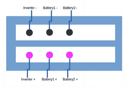
This is the wiring order on the busbar:
Inverter minus - battery1 minus - battery2 minus
Inverter plus - battery1 plus - battery2 plus

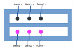
Is that wrong, and it should be "across" like this:
Inverter minus - battery1 minus - battery2 minus
battery1 plus - battery2 plus - Inverter plus

I believe that is what @robb2112 is saying but before I rewire I'd like to hear from others on this.
 
Last edited:
@hwy17 @Hedges @timselectric @sunshine_eggo @robbob2112 and anyone else:

This is the wiring order on the busbar:
Inverter minus - battery1 minus - battery2 minus
Inverter plus - battery1 plus - battery2 plus

Is that wrong, and it should be "across" like this:
Inverter minus - battery1 minus - battery2 minus
battery1 plus - battery2 plus - Inverter plus

I believe that is what @robb2112 is saying but before I rewire I'd like to hear from others on this.
That's typically how I've always used batteries in parallel from little li-ion cells to big honking flooded, forgot where I learned it but it's generally considered the way to equally charge/discharge.
 
@hwy17 @Hedges @timselectric @sunshine_eggo @robbob2112 and anyone else:

This is the wiring order on the busbar:
Inverter minus - battery1 minus - battery2 minus
Inverter plus - battery1 plus - battery2 plus

Is that wrong, and it should be "across" like this:
Inverter minus - battery1 minus - battery2 minus
battery1 plus - battery2 plus - Inverter plus

I believe that is what @robb2112 is saying but before I rewire I'd like to hear from others on this.

At this point, I really need to see a sketch. With bus bars in the mix, the "across" wiring means nothing if the batteries are connected to the bus bar with equal length wire.
 
At this point, I really need to see a sketch. With bus bars in the mix, the "across" wiring means nothing if the batteries are connected to the bus bar with equal length wire.
Here are the 2 options. First one is what I have now. 2nd one is what @robbob2112 is advocating (i believe)

ver1.png


Here's the 2nd option:


ver2.png
 
Option 3: Just swapping" battery 1-" with "battery 2-" from the first option would be my choice.

Inverter minus > battery2 minus > battery1 minus
Inverter plus > battery1 plus > battery2 plus


Minor edit as @Hedges's idea below is better ;)
 
If separate SCC, how is it wired in?

Different places to connect, some cause SCC or inverter to confuse each other with IR drop. Maybe a bigger deal for lead-acid with its charge profile.

I would think balancing both charge and discharge would be useful, since history of each would affect the other.
don't know, it might be the same unit, just saying that we should ask more questions before all jumping on the bandwagon. I honestly think most of this is much adieu about nothing, but support his desire to make it as perfect as possible.
 
Busbar seems pretty short, but why not put inverter in middle, one battery on either side, for perfect symmetry?


I thought of that originally, but then I considered the MPPT cables - if they are not part of the inverter then they would charge unevenly. And if there are any other loads besides the inverter they would discharge unevenly.

We are at the stage of ignore it and call it good or investigate because enquiring minds want to know.

If after switching the cables there is no change then I would use a YR1035 meter to measure the connections where they are crimped verse the other end of the wire. If there are deltas maybe recheck that the wires really are equal length, even an inch matter.

Use the same YR1035 to measure the internal battery resistance at the same state of charge.

To that end, if all wires are perfectly crimped and exactly the same length either forget about it all together... OR

make the wiring this - assuming B2 is the one that isn't charging as much. If the gripe follows then the battery just plain has higher impedance that B1 and it is enough higher to cause the problem.

Inv+ | B2+ | B1+
Inv1 | B2- | B1-

If you want to still reduce it - use the meter to make the cables slightly longer on B1 so that the total impedance matches when considered from the end that attaches to the bus bar. I've thought of this for cases where 6 batteries are hooked to a bus bar in a Z configuration. Make the top and bottom battery leads an inch longer than the middle ... basically whatever length of cables makes them balance impedance wise.
 
Last edited:
I thought of that originally, but then I considered the MPPT cables - if they are not part of the inverter then they would charge unevenly. And if there are any other loads besides the inverter they would discharge unevenly.

We are at the stage of ignore it and call it good or investigate because enquiring minds want to know.

If after switching the cables there is no change then I would use a YR1035 meter to measure the connections where they are crimped verse the other end of the wire. If there are deltas maybe recheck that the wires really are equal length, even an inch matter.

Use the same YR1035 to measure the internal battery resistance at the same state of charge.

To that end, if all wires are perfectly crimped and exactly the same length either forget about it all together... OR

make the wiring this - assuming B2 is the one that isn't charging as much. If the gripe follows then the battery just plain has higher impedance that B1 and it is enough higher to cause the problem.

Inv+ | B2+ | B1+
Inv1 | B2- | B1-

If you want to still reduce it - use the meter to make the cables slightly longer on B1 so that the total impedance matches when considered from the end that attaches to the bus bar. I've thought of this for cases where 6 batteries are hooked to a bus bar in a Z configuration. Make the top and bottom battery leads an inch longer than the middle ... basically whatever length of cables makes them balance impedance wise.
Just adding a fuse would change the resistance. Add another lol
 
don't know, it might be the same unit, just saying that we should ask more questions before all jumping on the bandwagon. I honestly think most of this is

Agreed. Cable lengths and consistency of connections matters more than busbar.
And lead-acid would care more.

Matching should only be an issue if you need the current handling of multiple batteries, and then I'm not sure there are guarantees (beyond IR of cells, but mismatched balancing could mess things up.)

much adieu about nothing

Freudian Slip, perhaps?

👋👋

I thought of that originally, but then I considered the MPPT cables - if they are not part of the inverter then they would charge unevenly. And if there are any other loads besides the inverter they would discharge unevenly.

I might stack MPPT wires to same bolts as inverter. Possibly on back side (I connected 4x inverter/chargers to 2x bolt holes that way.)
 
Don't anybody shoot me.... put away your guns, your knives, and anything else if your hands - BUT - A pure copper washer between the lug and bus bar of the stronger battery might shift things enough to balance it....

OK, we return you to your regularly scheduled program
 
Don't anybody shoot me.... put away your guns, your knives, and anything else if your hands - BUT - A pure copper washer between the lug and bus bar of the stronger battery might shift things enough to balance it....

OK, we return you to your regularly scheduled program
Only if you polish it first.
Screenshot_20240709-230046~2.png
 
@hwy17 @Hedges @timselectric @sunshine_eggo @robbob2112 and anyone else:

This is the wiring order on the busbar:
Inverter minus - battery1 minus - battery2 minus
Inverter plus - battery1 plus - battery2 plus

Is that wrong, and it should be "across" like this:
Inverter minus - battery1 minus - battery2 minus
battery1 plus - battery2 plus - Inverter plus

I believe that is what @robb2112 is saying but before I rewire I'd like to hear from others on this.
I maintain the attitude that parallel balancing does not need to be watched or catered to so I generally don't advise on symmetry. But you could post a diagram for easier digestion.

My wiring is unequal size, unequal length, and not wired across.
 
Oh ye of such wimpy inverter power!

Some of us have systems which easily exceed max current for any cell or BMS.

Consider my 23kW continuous, 44kW surge. Divide by 42V low battery to get 548A (continuous), 1048A (surge). And that's before applying efficiency or ripple factor.
That's why I don't bother with silly little LiFePO4 banks. I use lead-acid (AGM) with massive CCA.
(now if I only had loads so large, I would actually have a reason to gloat.)
 
@kolek no backdoor I'm not that clever besides if you truly start to use home assistant devices around the home to control loads etc I would suggest(if your router/firewall permits)putting everything on and insulated vlan that way nothing you use can report back to china with your bank details/sexual preferences.
 
@kolek no backdoor I'm not that clever besides if you truly start to use home assistant devices around the home to control loads etc I would suggest(if your router/firewall permits)putting everything on and insulated vlan that way nothing you use can report back to china with your bank details/sexual preferences.
this is a much better answer..not gong to comment on my initial reaction to your earlier post :ROFLMAO:
 

diy solar

diy solar
Back
Top