diy solar

diy solar

4 12V packs, 2 consistent voltage readings?

riverbug

New Member
Joined
Aug 5, 2021
Messages
92
I purchased two sets of Eve LF280 cells about 6 months apart. From each set I built 2 12V packs using JK BMS'. These are wired in parallel for my RV using all Victron components including 12/3000 120 Multiplus for charging, etc. The first two packs that I built will charge to 14.2V (which is what I have the Multiplus set up to charge to), but then quickly drop to 13.6V and stay there until they begin discharging (after removing shore power). The second two packs I built will charge to 14.2V and remain hovering at 14.1V and discharge from there. The two sets are consistently 5V different according to the JK BMS' no matter how long they are discharging or sitting idle with shore power.

I have verified that all the settings on each of the BMS' are identical. I initially had all packs attached to buss bars. I then removed the buss bars and wired them in parallel, making sure the system was attached at each end of the string and not from the same pack. Neither configuration made a difference in the V readings.

Any ideas what might be going on? I always thought that if batteries were connected in a string (whether series or parallel) they would automatically equalize with one another?

Thanks.
 
1st have you verified the bms readings with a meter like Fluke, Klein or Southwire?
2nd only in parallel will they try to equalize and at 0.5v difference it will take a long time.
 
Nothing WRONG HERE !
LFP will ALWAYS settle a bit post charge... You can charge them till you are BLUE IN THe FACE and the cells are taking 0A because they are full @ 3.5V per cell (14.0V) and they WILL settle to 3.4 Volts per cell (13.6V) if they are well matched & batched.

The reason is SIMPLE !.
LFP like ALL chemistries has 2 Voltage Curves.
1) The Allowable Range from 2.500-3.650 which is the Safe "No Harm No Dammage" voltage range. This is NOT to be used regularly, this is the "safe range".
2) The Working Voltage Range which is actually directly connected to the very flat voltage curve, his is the area that delivers the ACTUAL RATED AH of the cells, this is from 3.000-3.400 Volts per cell and hence WHY LFP Nominal Voltage is 3.200 or 50% SOC.

A proper charge profile is as follows:
Divide Values X2 for 12V. Multiply X2 for 48V.
Bulk/Absorb: 27.6 (3.45vpc) "Absorb Timer" to 45 minutes (some call this boost) *never actually runs the full 45mins because of EndAmps
Equalize: OFF
Float 27.5V (3.437vpc)
MIn Volts: 21.2 (2.650vpc)
Max Volts: 28.6 (3.575vpc)
Rebulk Voltage: 25.6 (3.200vpc)
End Amps: (*1) (** Allows for full Saturation at set Float Voltage)
(*1): End Amps is calculated IE: (100AH X 0.05 = 5A or 280AH X 0.05 = 14A.
EndAmps = TailCurrent
Coulumbic Efficiency / Battery Status Meter Efficiency for LFP = 99%.

From one of my resources.... handy to have available.
quick-voltage-chart-lfp-jpg.150247
Thanks much for this information. Looks like I could tweak my settings a bit based on this info; I need to double check my low voltage cutoff. But I'm still perplexed as to why two of my packs always sit at 14.1V and do not appear to ever settle to 13.6V like the other two?
 
1st have you verified the bms readings with a meter like Fluke, Klein or Southwire?
2nd only in parallel will they try to equalize and at 0.5v difference it will take a long time.
I do not own a Fluke or other expensive meter but I have checked them with the meter I have and the results are pretty much the same. Even if it isn't showing the exact voltage like a Fluke might, it certainly is showing that the two sets of packs are always 5V different from one another. One packs settles to 13.6V and the other never does; it aways remains at 14.1 as long as shore power is present and when shore power is removed, the two sets of packs remain 5V different from one another no matter how far I discharge them. That's the riddle I'm trying to figure out.
 
Believe it or not, could just be that they got better cells.

EVE 280's V1 hasn't been seen in 3 years or so. V2 came out and production ran for about a year, these made the grade but just. V3 came out and Big Change, they are generally better and most A-Grade 280K V3's are actually retaining between 295-305AH, whereas V2 at best held 285-295AH

Paralleling Battery Packs into a Battery Bank is not done properly can result in all sorts of peculiarities. The most effective way is to Parallel all battery packs to a Common DC Busbar system. !!! REAL BUSBAR - Not cheapo $50 pairs ! Personally I like PIKE Industries ones.
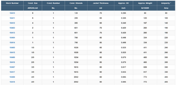
Wire used should be Fine to Ultrafine copper stranded wire. (Usually high quality welding wire like Royal Excelene.
(see table below for size, amp & strand-count )
Each battery to have identical length cables (excluding fuse/switches or devices).
Each battery to be fused to it's AH rating: IE 100AH battery = 100A fuse. With 12V/24V you can use MRBF Fuses at the Busbar...

Royal Excelene Wire Table: Made by SouthWire USA.
Excelene Wire Table.PNG
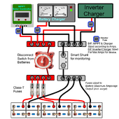
An A-Typical "generic" Component Solar System setup.
1704553517451.png
 
Thanks Steve. Sounds like I don't need to be concerned about the difference between the packs then. My configuration follows your diagram, including fusing, welding wire, etc., with one caveat that I have a T-Class fuse between the positive buss bar and cutoff switch (in addition to MRBF fuses mounted directly on each battery terminal). I do not have T-Class fuses at each battery.

Since It didn't seem to make a difference in the voltage variation when I removed the buss bars from the configuration, I'll go back to the original configuration with the buss bars and just not worry about why the voltages vary going forward. Thanks again!
 
I have one last question on this topic and then I'll let it rest... So, if a 12V LFP pack "should" settle at about 13.6V, but two of my packs remain constantly at about 14.0V - 14.2V, as long as I have a charge source (either solar or shore power), is that bad for the cells? Is it going to cause faster degradation than if they would settle to 13.6V as it seems most do?
 
That won't hurt anything although they should never gain more than the set Charge/Float voltage.
The moment charge stops, LFP starts to settle ad usually drops a little depending on the charge saturation...
As LFP cells fill up, Internal Resistance increases, lowering the Amps the cells will take. A 100AH battery is "technically full" with the EndAmps/Tailcurrent is reached which is 5A being taken by the battery packs.
In the Multiplus I have absorption set to 14.2 for 1 hour and float set at 13.6. As long as there isn't any concern that those two packs don't drop in voltage after absorption is reached then I guess I'm good to go. Thanks for all the responses and information; really appreciate your help!
 
I'm back with more questions and information. I believe I realize my original mistake as well. When I purchased my initial set of 8 cells to build my first two 12V packs, I fully intended to purchase a second set of 8 to build two additional packs. However, I thought I understood that LFP batteries were not as sensitive as lead-acid with respect to ensuring batteries are purchased at the same time for same age, same brand, same size, etc. I now assume that the problems I am having are completely related to not purchasing the 16 cells in the same order. I say this because packs 1 & 2 charge, discharge, and hold charge at about the same rate, and the same goes for packs 3 & 4 (with a bit more deviation from one another). My question now is, is there anything I can do to improve the situation short of purchasing 16 new cells and starting over (which ain't gonna happen)?

These packs are used in my RV. I have 1,000 watts of solar plus shore power (depending on location), but often not. I'm regularly pulling 125+ amps at 12V as we run the microwave, air conditioner, Instant Pot, Air Fryer, and whatever else. Although, we manage very well what runs at the same time. There may be 250A load for short periods but 90% of the time it's kept under 150A. We have a Victron 12/3000/120 Multiplus if that's useful.

At the moment we've been running off-grid for 3 days. According to my Victron Shunt I have used 350AH since last full charge and at 70% remaining capacity (on 1,120AH or 13.4KW). Looking at each JK BMS this is what I see...
Cell 1: 13.14V, 46% remaining capacity
Cell 2: 13.13V, 45% remaining capacity
Cell 3: 13.55V, 84% remaining capacity
Cell 4: 13.63V, 95% remaining capacity

When I built the packs I diligently tried to make sure I used the same torque specs across all cell connections, across the buss bars, etc. Would it be at all beneficial at this point to pull the packs apart, retest each cell to verify its AH capacity, and then try to match them in sets that would provide the closest AH capacity across all four packs regardless of which cells were originally purchased together? Not sure if that would improve anything or not. The BMS' have 2 amp balancers, and the cells in each pack are generally well balanced (.002 - .005V). I have set the balancers to start at 3.42V. The charge profile was modified to 13.8V bulk and absorption, and 13.6V float as @Steve_S suggested.

My concern is how much I'm exercising 2 of the packs while the other 2 get utilized much less. And I assume when the first 2 deplete, all the load is put on the remaining two until they deplete; although I haven't actually run them down that low yet. I'm sure I am not the first person to make an expensive mistake as I learn this stuff, but it sucks a little to think maybe it could have been avoided if I just purchased the cells at one time rather than 6 months apart.

Edited to bold my actual question since I buried it in this long dissertation. :)
 
Last edited:
Back
Top