


You are using an out of date browser. It may not display this or other websites correctly.
You should upgrade or use an alternative browser.
You should upgrade or use an alternative browser.
Doubling up cables
- Thread starter Fd9031
- Start date
crossy
Solar Addict
If you expect the cables to share the current equally then they must be the same resistance.
That would mean the same wire size and the same length.
Even then differences in the crimp connections would affect the current in each.
That would mean the same wire size and the same length.
Even then differences in the crimp connections would affect the current in each.
pollenface
Solar Wizard
I double up as needed if i don't have any phat cable for what I'm doing ")
Bananaman321
⚡solar idiot ⚡
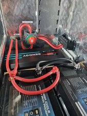
Doubling conductors is fine just make sure all crimps are good-n-tight and connections are clean and torqued with no-ox inhibitor between all layers not necessary on crimps. Make sure to double check all connections for tightness.Is this setup OK so far. I have read that doubling up cables should be the same.
More precisely, the resistance to each battery should be the same. Yours are not. The battery on the right has an extra length of cable and an extra junction to traverse, compared to the battery on the left. In your setup, the battery on the left will pull much more of the load than the other one.I have read that doubling up cables should be the same.
I can’t see the rest of your setup, but my guess is that a better setup would be equal length cables from each battery to the busbar, then from the busbar go to the fuse and switch, then to the CC/Inverter.
Bananaman321
⚡solar idiot ⚡
As long as it is fused properly it won't matter
Equal conductor length only applies when paralleling batteries
Positive and negative cables appear to be equal length
Equal conductor length only applies when paralleling batteries
Positive and negative cables appear to be equal length
Last edited:
Another alternative would be a single cable from each battery directly to the stud on the fuse block. Preferably, the same length for each battery. That would give you about the same total current-carrying capacity you’ve got now, but better equalized between batteries.
Thanks for that, I will make the cables as close as possible to the same length and and take another photo. As for the setup, that's where I'm at the momentMore precisely, the resistance to each battery should be the same. Yours are not. The battery on the right has an extra length of cable and an extra junction to traverse, compared to the battery on the left. In your setup, the battery on the left will pull much more of the load than the other one.
I can’t see the rest of your setup, but my guess is that a better setup would be equal length cables from each battery to the busbar, then from the busbar go to the fuse and switch, then to the CC/Inverter.
Yes, cable is very expensive, so I thought I would double up as this is what I gotAnother alternative would be a single cable from each battery directly to the stud on the fuse block. Preferably, the same length for each battery. That would give you about the same total current-carrying capacity you’ve got now, but better equalized between batteries.
Those batteries are in parallel, aren’t they? Certainly appear that way.Equal conductor length only applies when paralleling batteries
Bananaman321
⚡solar idiot ⚡
Yes they are in parallel in that configuration one conductor will only carry slightly more current than the other one no problem here at all
Last edited:
Texas-Mark
Solar Wizard
- Joined
- Aug 4, 2021
- Messages
- 1,549
the battery on the left will pull much more of the load than the other one.
Much more?? Come on, those cables are so short to begin with any resistance difference is beyond negligible.
Also, has anyone elver looked at the size of the BMS leads inside those batteries? I would be more concerned about the resistance and current capabilities of those.
Bananaman321
⚡solar idiot ⚡
The only real concern is that the same amount of current flows through both batteries the jumper cables between the 2 batteries are the same length so the same amount of current will flow between both batteries
Bananaman321
⚡solar idiot ⚡
Did you know you can parallel conductors of different sizes
You just add the 2 current carrying capacities and they become one
You just add the 2 current carrying capacities and they become one
As long as it is fused properly it won't matter
exactly.My preference in that situation would be to fuse each cable individually, according to its capacity. If you have one fuse supplying two parallel cables there is always the risk that one cable connection fails and all the current flows through the one remaining cable, which is then incorrectly fused. That's probably impractical with your configuration though.
Bananaman321
⚡solar idiot ⚡
Sure I'll go with that
My preference in that situation would be to fuse each cable individually, according to its capacity. If you have one fuse supplying two parallel cables there is always the risk that one cable connection fails and all the current flows through the one remaining cable, which is then incorrectly fused. That's probably impractical with your configuration though.
As long as the 2 conductors as a whole are not overloaded they will carry their own respective value
For those that don't know
You should know better than this even two conductors the same size won't become one, temperature coefficient plays a large role and as this is in a battery box you should expect both conductors to carry 166% of a single conductor even two conductors spread 30cm apart should be thought of as 180%Did you know you can parallel conductors of different sizes
You just add the 2 current carrying capacities and they become one
I said cables should be identical as OP has a single fuse any longer cables will be considered a weak link since it's a DIY forum and were talking parallel batteries best to just say that all cables should be identical.
Texas-Mark
Solar Wizard
- Joined
- Aug 4, 2021
- Messages
- 1,549
You should know better than this even two conductors the same size won't become one, temperature coefficient plays a large role and as this is in a battery box you should expect both conductors to carry 166% of a single conductor even two conductors spread 30cm apart should be thought of as 180%
You are assuming one is maxing out the current capabilities. And IMO you are severally underestimating the capabilities when doubling up conductors because the resistance at those lengths is negligible.
Of course I'm assuming op hasn't stated otherwise, I'm British and we used to use doubled conductors in every household two 20 amp conductors fused at 32amps feed the sockets it was 30 years ago since I did any training so I don't remember the science but it was drummed into us that using two conductors won't double the current carrying capacity and that's at relatively high voltage and low amperage compared to OP`s 12v and I'm guessing 100amp+ so I'm sticking to the basics in what I know.You are assuming one is maxing out the current capabilities. And IMO you are severally underestimating the capabilities when doubling up conductors because the resistance at those lengths is negligible.
Texas-Mark
Solar Wizard
- Joined
- Aug 4, 2021
- Messages
- 1,549
Am I the only one who doesn’t like 4x lugs on one terminal?
For something like this, I don't see a problem. I've done it when using a busbar is not feasible or the best option.
robbob2112
Doing more research, mosty harmless
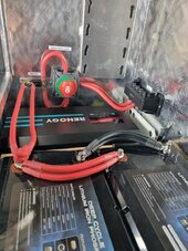
First - looking at the picture - this is a clear cut case of the OP needs to just buy 3 sizes bigger wire and loose the double cables.
Double cables are fine for the times when you just run out of wire and you MUST have it done and working. And you promise yourself you will buy the right sized wire to replace it before you buy your next beer.
The rest is a bit of a novel but important to understanding the problem.
Equal conductor length absolutly matters for 2 parallel lines running from point A to point B. They will carry current unevenly and that needs to be minimized.
And since both lines must be fused for half the current it affects how they blow. Unless specifically using matched fuses they blow at different times. Without matched fuses the time/current curves are totally out to lunch for both of them. Matched fuses are typically sold as 2 soldered together with one set of tabs to bolt down or one blade to insert.
Fuses like the class T or MRBF which are quick acting will carry double current for 10 minutes for blowing. To get quicker blow times it takes 6 times the current and the time is 0.01 to 0.001 seconds.
So lets figure 4 awg welding wire rated at 105c - max current is 150amps. To get the same amount of copper you increase 3 sizes - so 1/0 wire. Same brand and the 1/0 is rated at 285 amps.
So the 1/0 carries 95% of the current of two 4awg wires. This is because 2 x 4 awg wires have more surface area for cooling to happen.
0.4in²*π = 0.502in * 2 = 1.005in
0.56in²*π = 0.98in
0.98/1.005 * 100 = 97.5%
So, now you think - great I will double up all my wires and they will be cooler. But, now look at the resistance
And, just like with batteries with uneven internal impedance there will be a small but noticable difference in current carried..
4/0 wire has 0.0314Ω per thousand foot
4 awg has 0.0792Ω per thousand foot
so - 2 x 4awg has 0.0396Ω per thousand foot.
Now do the math for 2ft of each setup carrying 150amps. Both class T JLLN style.
Of course the 4/0 carries 150amps - fuse at 175amps - 120% capacity
A short blows the fuse and you are done.
But lets assume a 2 inch difference in length for the 4 awg cables - not really a big deal as the math shows.
wire1 current =4.82×10⁻⁵Ω0.003615V≈75.00A
wire2 current =4.93×10⁻⁵Ω0.003615V≈73.33A
So you fuse them both at 90 amps individually and walk away.
The time/current curve shows it will carry 330amps for 20 second.
Now assume there is a quick short on one cable, slipped screwdriver - might blow both fuses might just blow one if the short is near the battery end.
Assume it blows just one and lets see what happens to the other wire in 20 seconds. It will last longer but cooling would have to be taken into account across time and my calculus card has been revoked.
I did the calculation and can share them if you want, but in 20 seconds the wire is 119c (246f) or 14c past the safe point of the sheath and it is either melting or burning - hard to say exactly but the results aren't good and the chances of a second short are now almost certain.
The wire length difference of 2" didn't really make a difference, but having 2 wires did.
Now next increase the difference to 12" - so one wire is 2ft and the other is 3ft
This time the same math applies but the 2ft wire is carrying 90 amps and the 3ft one is carrying 60 amps. So what do you fuse them at?
So the correct answer on doubling up wires is keep them as close to identical as possible in length and size.
And a table to show what happens - a little spreadsheet help here with lots of rounding

Never stack lugs if you can help it, if you can't help it no more than 2 lugs per terminal. If you have 4 lugs on one terminal you need to be using a bus bar.
Stacking lugs makes for imperfect current transfer the higher you go up the stack and there will be hot spots.
In the picture it sure looks like a bus bar would fit if there is no way to just remake the cables with larger wire.
And my last note to the OP - Did you clean all surfaces and use no-ox-id special , or equivalent, on all the mating surfaces? This inhibits corrosion and makes for a better connection.
Double cables are fine for the times when you just run out of wire and you MUST have it done and working. And you promise yourself you will buy the right sized wire to replace it before you buy your next beer.
The rest is a bit of a novel but important to understanding the problem.
As long as it is fused properly it won't matter
Equal conductor length only applies when paralleling batteries
Positive and negative cables appear to be equal length
Equal conductor length absolutly matters for 2 parallel lines running from point A to point B. They will carry current unevenly and that needs to be minimized.
And since both lines must be fused for half the current it affects how they blow. Unless specifically using matched fuses they blow at different times. Without matched fuses the time/current curves are totally out to lunch for both of them. Matched fuses are typically sold as 2 soldered together with one set of tabs to bolt down or one blade to insert.
Fuses like the class T or MRBF which are quick acting will carry double current for 10 minutes for blowing. To get quicker blow times it takes 6 times the current and the time is 0.01 to 0.001 seconds.
So lets figure 4 awg welding wire rated at 105c - max current is 150amps. To get the same amount of copper you increase 3 sizes - so 1/0 wire. Same brand and the 1/0 is rated at 285 amps.
So the 1/0 carries 95% of the current of two 4awg wires. This is because 2 x 4 awg wires have more surface area for cooling to happen.
0.4in²*π = 0.502in * 2 = 1.005in
0.56in²*π = 0.98in
0.98/1.005 * 100 = 97.5%
So, now you think - great I will double up all my wires and they will be cooler. But, now look at the resistance
And, just like with batteries with uneven internal impedance there will be a small but noticable difference in current carried..
4/0 wire has 0.0314Ω per thousand foot
4 awg has 0.0792Ω per thousand foot
so - 2 x 4awg has 0.0396Ω per thousand foot.
Now do the math for 2ft of each setup carrying 150amps. Both class T JLLN style.
Of course the 4/0 carries 150amps - fuse at 175amps - 120% capacity
A short blows the fuse and you are done.
But lets assume a 2 inch difference in length for the 4 awg cables - not really a big deal as the math shows.
wire1 current =4.82×10⁻⁵Ω0.003615V≈75.00A
wire2 current =4.93×10⁻⁵Ω0.003615V≈73.33A
So you fuse them both at 90 amps individually and walk away.
The time/current curve shows it will carry 330amps for 20 second.
Now assume there is a quick short on one cable, slipped screwdriver - might blow both fuses might just blow one if the short is near the battery end.
Assume it blows just one and lets see what happens to the other wire in 20 seconds. It will last longer but cooling would have to be taken into account across time and my calculus card has been revoked.
I did the calculation and can share them if you want, but in 20 seconds the wire is 119c (246f) or 14c past the safe point of the sheath and it is either melting or burning - hard to say exactly but the results aren't good and the chances of a second short are now almost certain.
The wire length difference of 2" didn't really make a difference, but having 2 wires did.
Now next increase the difference to 12" - so one wire is 2ft and the other is 3ft
This time the same math applies but the 2ft wire is carrying 90 amps and the 3ft one is carrying 60 amps. So what do you fuse them at?
So the correct answer on doubling up wires is keep them as close to identical as possible in length and size.
And a table to show what happens - a little spreadsheet help here with lots of rounding
Am I the only one who doesn’t like 4x lugs on one terminal?
Never stack lugs if you can help it, if you can't help it no more than 2 lugs per terminal. If you have 4 lugs on one terminal you need to be using a bus bar.
Stacking lugs makes for imperfect current transfer the higher you go up the stack and there will be hot spots.
In the picture it sure looks like a bus bar would fit if there is no way to just remake the cables with larger wire.
And my last note to the OP - Did you clean all surfaces and use no-ox-id special , or equivalent, on all the mating surfaces? This inhibits corrosion and makes for a better connection.
Last edited:
I do appreciate it when someone backs up myFirst - looking at the picture - this is a clear cut case of the OP needs to just buy 3 sizes bigger wire and loose the double cables.
Double cables are fine for the times when you just run out of wire and you MUST have it done and working. And you promise yourself you will buy the right sized wire to replace it before you buy your next beer.
The rest is a bit of a novel but important to understanding the problem.
Equal conductor length absolutly matters for 2 parallel lines running from point A to point B. They will carry current unevenly and that needs to be minimized.
And since both lines must be fused for half the current it affects how they blow. Unless specifically using matched fuses they blow at different times. Without matched fuses the time/current curves are totally out to lunch for both of them. Matched fuses are typically sold as 2 soldered together with one set of tabs to bolt down or one blade to insert.
Fuses like the class T or MRBF which are quick acting will carry double current for 10 minutes for blowing. To get quicker blow times it takes 6 times the current and the time is 0.01 to 0.001 seconds.
So lets figure 4 awg welding wire rated at 105c - max current is 150amps. To get the same amount of copper you increase 3 sizes - so 1/0 wire. Same brand and the 1/0 is rated at 285 amps.
So the 1/0 carries 95% of the current of two 4awg wires. This is because 2 x 4 awg wires have more surface area for cooling to happen.
0.4in²*π = 0.502in * 2 = 1.005in
0.56in²*π = 0.98in
0.98/1.005 * 100 = 97.5%
So, now you think - great I will double up all my wires and they will be cooler. But, now look at the resistance
And, just like with batteries with uneven internal impedance there will be a small but noticable difference in current carried..
4/0 wire has 0.0314Ω per thousand foot
4 awg has 0.0792Ω per thousand foot
so - 2 x 4awg has 0.0396Ω per thousand foot.
Now do the math for 2ft of each setup carrying 150amps. Both class T JLLN style.
Of course the 4/0 carries 150amps - fuse at 175amps - 120% capacity
A short blows the fuse and you are done.
But lets assume a 2 inch difference in length for the 4 awg cables - not really a big deal as the math shows.
wire1 current =4.82×10⁻⁵Ω0.003615V≈75.00A
wire2 current =4.93×10⁻⁵Ω0.003615V≈73.33A
So you fuse them both at 90 amps individually and walk away.
The time/current curve shows it will carry 330amps for 20 seconds.
Now assume there is a quick short on one cable, slipped screwdriver - might blow both fuses might just blow one if the short is near the battery end.
Assume it blows just one and lets see what happens to the other wire in 20 seconds.
I did the calculation and can share them if you want, but in 20 seconds the wire is 119c (246f) or 14c past the safe point of the sheath and it is either melting or burning - hard to say exactly but the results aren't good and the chances of a second short are now almost certain.
The wire length difference of 2" didn't really make a difference, but having 2 wires did.
Now next increase the difference to 12" - so one wire is 2ft and the other is 3ft
This time the same math applies but the 2ft wire is carrying 90 amps and the 3ft one is carrying 60 amps. So what do you fuse them at?
So the correct answer on doubling up wires is keep them as close to identical as possible in length and size.
And a table to show what happens - a little spreadsheet help here with lots of rounding
View attachment 228761
Never stack lugs if you can help it, if you can't help it no more than 2 lugs per terminal. If you have 4 lugs on one terminal you need to be using a bus bar.
Stacking lugs makes for imperfect current transfer the higher you go up the stack and there will be hot spots.
In the picture it sure looks like a bus bar would fit if there is no way to just remake the cables with larger wire.
And my last note to the OP - Did you clean all surfaces and use no-ox-id special , or equivalent, on all the mating surfaces? This inhibits corrosion and makes for a better connection.

 with science.
robbob2112
Doing more research, mosty harmless
Looked again and apparently I have another comment -
Each battery should have a MRBF fuse on the positive post for 20% over what the BMS will put out.
I really really dislike ANL fuses - they generate a lot of wasted heat - they are great in a car stereo install, but not in a battery install. In car audio the amp is constantly changing the current drawn with a boom - boom - boom... the average of the booms over time is MUCH lower than the amount of current you fuse for so ANL doesn't really heat up so much.
With batteries and inverters you are also changing, but the constant load is more even and higher than an audio amplifier. So you loose a lot of energy to heat.
I would suggest replacing the ANL with a class T of the appropriate size for the inverter.
Similar threads
- Replies
- 2
- Views
- 236
- Replies
- 1
- Views
- 227
- Replies
- 15
- Views
- 681
- Replies
- 6
- Views
- 523
- Replies
- 4
- Views
- 476