diy solar

diy solar

BMS common port vs seperate port

Hi,

Just read the whole thread, interesting topic. Sorry if my question doesn't directly concern solar application.
I would like to build a lifepo4 12V pack to eventually replace a lead acid battery in a car...

I 'm looking to buy a DALY BMS and need to choose between common or separate.
With traditionnal lead acid, charge and discharge are done from same port so I would say the common version would be more appropriated here...
(it seems that we cannot use a separate version and still charge and discharge from same physical port?)
My concern with common port is about overcharge. It is specified from specs charge voltage is 14.6V, which I think should be close to what a car provide generally. Do you think there would still be risk of overcharge and battery disconnection?

Also I'm wondering which amperage should be taken.
From the specs, it is specified 100A version has 300A sparkle current (not sure to know exactly what it means) .
As lots of current is only going to be required at start, and for a few seconds, I wonder if 100A version would be enough.
Do you know if BMS would handle any momentary extra current or if it will go to overcurrent protection and forbid the car from starting??

Thanks
Most cars take about 400 to 600amps on start up.
You would need a monster bms to be able to deliver that,
On the other hand i think i have seen bms with 5 sec surge ratings of 2x the rated current, if true, you may be able to get away with a 300amp bms.

Curious why you want to put lifepo4 in a car, when a conventional leadacid does the job nice and cheap.
 
Curious why you want to put lifepo4 in a car, when a conventional leadacid does the job nice and cheap.
I am also curious about this. I think its worth thinking hard about the pros/cons before pursuing. Two other issues are low temperatures, and the consequences of a BMS disconnecting (will it harm the alternator?)

LTO (another lithium chemistry solves the first problem but not the second.
Most cars take about 400 to 600amps on start up.
You would need a monster bms to be able to deliver that,
On the other hand i think i have seen bms with 5 sec surge ratings of 2x the rated current, if true, you may be able to get away with a 300amp bms.
Yes some FET based BMS' advertise surge ratings (not sure how much I would trust them)

Relay based BMS' are probably a more realistic/robust option.
 
I am also curious about this. I think its worth thinking hard about the pros/cons before pursuing. Two other issues are low temperatures, and the consequences of a BMS disconnecting (will it harm the alternator?)

LTO (another lithium chemistry solves the first problem but not the second.

Most of the people who are using LTO in a vehicle are the ones wanting 10 gazillion watts for an audio system. LTO has such a wide range in their charge profile that when used in a vehicle a BMS is not needed. Most of those audio guys are just using an aggressive balancer and no BMS.
LTO is what I would use if I were going looking for an exotic vehicle battery. Their current capacity and wide temperature range are impressive. You can also run them completely dead with no damage to the cells.
I would have used LTO for my RV pack if they were less expensive .... There is some indication that they are coming down in price.
 
  • Like
Reactions: Dzl
Thanks for replies.
I know it may seems going off the beaten path but I got the idea from this video notably

Most cars take about 400 to 600amps on start up.
You would need a monster bms to be able to deliver that,
I have quite small car and checking alternator specs, it seems to be rated at 1200W/1400W.
So I thought 100A @12V would be matching the 1200W requirement.
On the video posted above, I think the guy is using 200A BMS.

On the other hand i think i have seen bms with 5 sec surge ratings of 2x the rated current, if true, you may be able to get away with a 300amp bms.
Do you refer as what is labeled as 'sparkle current' on DALY BMS specs?
Here for 100A BMS they state 300 A sparkle current. (I'm sending an inquiry to the store to have more infos)
Curious why you want to put lifepo4 in a car, when a conventional leadacid does the job nice and cheap.
The reason is mainly curiosity and DIY...
Also LifePo4 could be a nice replacement for traditional car batteries because of their increased lifetime:
5 times more than a lead acid one (they can support 2000-3000 cycles, when acid is around 500-800 I think)

Regarding the temperature, I saw someone building one for his motorbike, it seems in cold temperature to a bit hard to start, but still he managed to do it apparently. (video is in french)

I'm going to look at LTO
 
Regarding the temperature, I saw someone building one for his motorbike, it seems in cold temperature to a bit hard to start, but still he managed to do it apparently. (video is in french)

I'm going to look at LTO
The issue with temperature isn't the ability to start the vehicle, its that charging at low temperature (at or near freezing) will damage a LFP battery.
 
sparkle current and EV ?
I guess this is bad chinese translation, probably refering to surge current instead.

The issue with temperature isn't the ability to start the vehicle, its that charging at low temperature (at or near freezing) will damage a LFP battery.
Hmm didn't know that, will check if could be an issue in winter.
I know some very expensive car batteries are sold using LFP(or LifePO4, it is the same) but don't know how they perform in daily use.
Maybe they aren't popular for whom lives in cold region
 
I guess this is bad chinese translation, probably refering to surge current instead.


Hmm didn't know that, will check if could be an issue in winter.
I know some very expensive car batteries are sold using LFP(or LifePO4, it is the same) but don't know how they perform in daily use.
Maybe they aren't popular for whom lives in cold region
Some 'cold weather' lifepo4 batteries have builtin heating elements to keep the cells at a healthy temperature. This may be the case. If I were looking at replacing Lead Acid car battery with something else, I would look at LTO, it has a handful of properties that I would think make it better suited for that purpose than LFP
 
Most cars take about 400 to 600amps on start up.
You would need a monster bms to be able to deliver that,
On the other hand i think i have seen bms with 5 sec surge ratings of 2x the rated current, if true, you may be able to get away with a 300amp bms.

Curious why you want to put lifepo4 in a car, when a conventional leadacid does the job nice and cheap.
I was thinking about what you are commenting on and it has occurred to me to think, if so much power is needed, how is a small battery capable of starting a vehicle like the ones sold now? like this:
1605340070393.png
 
View attachment 665

Además, publiqué esto en otro lugar hace algún tiempo:

Actualización rápida para sistemas avanzados de células crudas LiFePO4 utilizando un Daly BMS:
En mi sitio web, recomendé usar un puerto BMS separado para protección contra sobretensión para la conexión mppt (si se usa el puerto común BMS, existe la posibilidad de destruir mppt durante la desconexión por bajo voltaje).

Bueno, ayer, un espectador y yo finalmente recibimos nuestro puerto BMS separado de Daly, y la clasificación del amplificador no era la que se anunciaba en la lista. ¡El puerto separado solo puede manejar 10 amperios!:(

Teniendo en cuenta la probabilidad de una situación de sobrevoltaje de la mayoría de los mppt de alta calidad, y la posibilidad de que las celdas LiFePO4 coincidentes se desequilibren es rara (y BMS corregirá la deriva de la celda con el tiempo), y que LiFePO4 puede sobrecargarse a 4.2v por celda antes de la degradación del electrolito ... Yo diría que es seguro conectar el mppt directamente al banco de baterías y evitar el BMS por completo. Lo hemos estado haciendo de esta manera durante años, pero la gente todavía quiere usar un BMS.

Yo diría que use BMS para cargas y no para cargadores. Si tiene celdas que no coinciden y algunas alcanzan un voltaje más alto con un SOC alto más rápido que otras, reduzca el voltaje límite superior de su controlador. 14.0-14.2v es un voltaje de carga seguro que puede proporcionar una capacidad total con LiFePO4 12v.

¡Espero que esto ayude! Apuesto a que la mayoría de las personas que construyen estos sistemas se darán cuenta de esto cuando vean este problema, pero si usted es un principiante que intenta construir un sistema de nivel avanzado, esta información será muy útil. Hazme saber si tienes al

Estoy algo confundido con esta información, ¿es posible que sea algo antiguo? y que el nuevo bms de puerto separado puede manejar 40/50 amperios a través del puerto de carga?


guna preguntaE

View attachment 665

Also, I posted this elsewhere sometime ago:

Quick update for advanced LiFePO4 raw cell systems using a Daly BMS:
On my website I recommended using a separate port BMS for over voltage protection for the mppt connection (if common port BMS is used, possibility of destroying mppt during low voltage disconnect).

Well yesterday, a viewer and I finally received our separate port BMS from Daly, and the amp rating was not as advertised on the listing. The separate port can only handle 10 amps! :(

Considering the likelihood of over voltage situation from most high quality mppt, and the chance of matched LiFePO4 cells going out of balance is rare (and BMS will correct for cell drift over time), and that LiFePO4 can be over charged to 4.2v per cell before electrolyte degradation... I would say its safe to connect mppt directly to the battery bank, and bypass the BMS entirely. We have been doing it this way for years, but people still want to use a BMS.

I would say use BMS for loads, and not for chargers. If you have mismatched cells, and some hit a higher voltage at high SOC quicker than others, drop the upper limit voltage of your controller. 14.0-14.2v is a safe charging voltage that can give full capacity with LiFePO4 12v.

I hope this helps! I bet most people building these systems will figure this out when they see this problem, but if you are a beginner trying to build an advanced level system, then this bit of information will be very useful. Let me know if you have any questions
I am somewhat confused with this information, is it possible that it is something old? and that the new separate port bms can handle 40/50 amps through the charging port?

Like this:
1605340503224.png 1605340601695.png
 
I was thinking about what you are commenting on and it has occurred to me to think, if so much power is needed, how is a small battery capable of starting a vehicle like the ones sold now? like this:
View attachment 27482
I believe the answer to that is ‘capacitors’. There are people using LiFePo4 for vehicle starting, by adding capacitors. DCS is a brand of drop in replacement that is warranted for engine cranking and winching, which makes me think they are doing without capacitors. Most lithium drop in replacements aren’t warranted for use under the bonnet, the DCS does but at reduced life. Curious to know how the difference between theirs and others.
 
The split port has a charge port and a battery port. The BMS can cut off Charge separate of battery (Load). The common port the load and charge port are together. If the split port sees high voltage It can shut off charging. If it sees low voltage, It can disconnect load.
At the start of this thread, I thought I understood the difference between common and seperate port. The above post seemed to make it quite clear, the BMS would disconnect the battery from both load and charge for either an under or over voltage situation. Presumably this requires some form of intervention to reset the BMS, like applying a charge voltage to a depleted pack.

On the last couple of pages though, it’s been stated (or implied?) that a common port still has directional smarts, so a low voltage situation will still allow charge current, and high voltage will still permit load current. If this is the case, what is the point of seperate ports?
 
Mine is a common port that allowed me to set different maximum current for charge and discharge direction. And even though it is on the same physical wire, it can block charge when the voltage is high, or block load when the voltage is low, but still allow the other direction so a low batt can be charged etc.
For example^
 
At the start of this thread, I thought I understood the difference between common and seperate port. The above post seemed to make it quite clear, the BMS would disconnect the battery from both load and charge for either an under or over voltage situation. Presumably this requires some form of intervention to reset the BMS, like applying a charge voltage to a depleted pack.

On the last couple of pages though, it’s been stated (or implied?) that a common port still has directional smarts, so a low voltage situation will still allow charge current, and high voltage will still permit load current. If this is the case, what is the point of seperate ports?
Without going back and reading the last couple pages (so I may miss some context) here are some generalized clarifications:

The terminology is confusing because there are two overlapping concepts here (1) the physical layout of the BMS (2) and the practical operation of the BMS (directional control or not). Customers and manufacturers/sellers mean different things by the same terms which confuses the issue.

I think @FilterGuy's terminology is the best imperfect terminology we have so far.
Common Port: A single wire connected to a single common port for charge/discharge, and no ability to control direction current. The battery is either connected or disconnected.
Separate Port: Two wires connected to 'separate ports', one for charge current the other for discharge current. Directional control is possible due to separate current paths
Hybrid Port: the layout of common port (single wire, single common port) but the functionality of separate port (directional control is possible).

In my eyes the terms separate and common port are imperfect and most relevant to Daly where the distinction is clear and there are only the two types. It gets messy when Hybrid port BMSes are brought into the mix. It is this third option (Hybrid port) that people are referring to when they say they have a common port BMS and also say they can control charging or discharging independently.

An example of a common port BMS is the basic Daly common port BMS
An example of a separate port BMS is the basic Daly separate port BMS
An example of a Hybrid Port BMS is the Overkill Solar (JBD Smart) BMS

This resource is worth a read


I think I got the basics of that right. Someone correct me If I miss the mark on any points.
 
This resource is worth a read
That’s a great document thanks Dzl.
Good to confirm many things I already kind of got and introduce new stuff too. Concept I was missing until now is the hybrid, which seems like the way to go for my (mobile) application. Second choice would be the common port which is kind of lucky because I’ve already (impulse) bought a Daly 200A common port. I don’t think the ‘wake up’ intervention (for low volts) would be a big deal because I can close a breaker and direct charge from the alternator for a bit. I’ve read people’s concerns about direct charge from alternator but think it’s manageable in my case.
 
Way back on the first page Will says
"and that LiFePO4 can be over charged to 4.2v per cell before electrolyte degradation..."

Well mate in fact 4.2 volts is around the ignition voltage for the ethylene carbonate electrolyte , so good luck selling that one .

In fact it seems that above 3.6v a molecular sludge is laid down over the plates and does not come back off so stay under 3.5 volts folks
 
The other thing that's worth a mention is LFP in cars .
You guys need to get out more and try stuff before posting crap .

I'm not affected by low temps as frost is possible but rare in Queensland where I live .

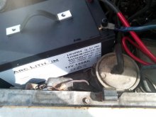
I have a 135 Ah LFP in my mitsubishi wagon on the farm because it is reliable and will likely last 10 years not 3 . It cost twice as much ..$399 AUD and is limited in its discharge ability to about 40 Amps continuous . I can flatten it completly and it will come straight back .

My car being a 4 cylinder petrol only draws about 40 amps on the starter and as the voltage does not sag it takes less amps in fact. The blurb on the BMS says it will discharge 125 Amps for 5 seconds before cutting off. I can change the BMS if I want.

I tried it on a 3 cylinder Detroit diesel and the battery would not take the draw. I'm guessing the higher compression needs more amps to the starter.
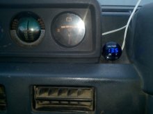
I watch the voltage on a digital voltmeter on the dash and if it gets up to its top voltage of 14.6 volts I switch the battery off,car keeps running of course. .It gets there after about half an hour of running because the regulator is faulty atm and I can't get to the field wire of the alternator in this model because the air conditioner sits above it . I will fix that at some point .

So in practice if I let it go past 14.6 volts the BMS will switch off and believe me this crap about alternator fields collapsing and destroying alternators used to work 30 years ago and many an auto electrician has conned his customers with that , but alternators have moved on and some have up to 17 diodes in them . Any collapsing field is taken straight to ground and there are no surges .

Discount the doomsayers , they have not done it.!
I'm looking forward to getting LFP in all my road cars.
There is a guy in Hong Kong putting them into all sorts of cars . LFPHK or something like that on facebook.
For more on LFP go here and join
 

Attachments

  • IMG_20201203_183626.jpg
    IMG_20201203_183626.jpg
    53.9 KB · Views: 12
  • IMG_20201111_085517.jpg
    IMG_20201111_085517.jpg
    45.7 KB · Views: 12
  • IMG_20201111_085535.jpg
    IMG_20201111_085535.jpg
    61.6 KB · Views: 12
Last edited:
and that LiFePO4 can be over charged to 4.2v per cell before electrolyte degradation.
Hi Will, I am designing and manufacturing BMS Systems for Winston LiFeYPO4 cells here in Germany. These cells can be charged to voltages up to 4.2 Volts. I was under the impression, that normal LiFePO4 cells like Calb Cannot be charged that high. Specs say that the charge cut off voltage is 3.6 Volts.
Can you point me to a source, which confirms the 4.2 Volts you mentioned. Thank you so much!
Hans
 
Back
Top