diy solar

diy solar

Chargery 8s SOC 280Ah too low & doesn't match Bogart

mkaye

New Member
Joined
Mar 23, 2020
Messages
278
i have had the system working all summer
for the past few weeks my RV was sitting in the driveway
so, just the standard 12V drain overnight & then the 200W of roof solar would charge things back up
i wanted to run the inverter a bit to drain the LFP battery lower to take it out for storage
it wouldn't power on, i then noticed i had no 12V, Chargery was blinking LOW SOC
but my Bogart display still showed 90%
overall battery voltage was 13.1V - all cells normal, SOC was not <10%

i had noticed that the Chargery SOC was slowing getting lower than the Bogart, but now it was a problem
both use the same Bogart shunt

how can get the Chargery SOC back to the correct state?

mark

running V4 firmware, but not the latest with the newer current GUI
 
On the Bogart Shunt, so you have monitoring on it like the Trimetric ?
The shunt only reads what passes through the (-) line be it charge / discharge.
The BMS also looks at the cells (shunt does not obviously) and does calculations based off that.
If the BMS is doing any passive balancing, that is "internal" and the shunt will not see any of that. So if you are passive balancing (even in storage) that can reduce the battery pack voltage down to the Lowest Cell Voltage within the pack.

Here comes a GOTCHA... Depending on Cell Size in AH, passive balancing can work or be a detriment. It is terribly slow and only burns off High Volt cells to match them down to the lowest cell. 1.2A does not move much quickly. When NOT in use, Balancing is better to have OFF. Balance while charging is the most neutral. Also make sure that your allowable Voltage Difference allows or 1mv per AH. So a 100AH Pack 100mv differential potential (that is within spec) and expected.

This is the Tricky Part with Battery monitors. Most of them are incapable of "seeing" the battery pack & cells, they only register Volts going out and coming in and then do the math accordingly. They have no way to see what is actually happing within the battery pack itself, as none of that happens on the line it watches. Then IF you have more than One Pack in a battery bank, that further confuses things for the Battery Monitor(s)

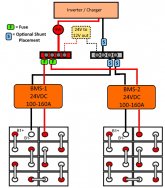
Example Image:
Basic 24V Parallel Bank.jpgHere we have 3 shunts shown.
The 2 on the Battery Side of the DC-Bus will only read Volts in/out to their specific battery pack and that is for the BMS to do it's thing.

The 1 Shunt on the Inverter Side (which should also have the SCC going through it) will see Volts going In/Out for the Whole Battery Bank. This would provide the Overall Status view of your SOC.

The "Inverter shunts" used with the BMS which reads the individual cells will be more accurate as to knowing the State of their pack.

I am not aware of a shunt / battery monitoring that can look at all cells in all packs and report total info on the state. Now if you were using a Distributed BMS that could do such things BUT those are the really pricey units (think Batrium etc).

And for something Completely Different.... An intermediary Device like Raspberry Pi which can be programmed to read the data output from the Chargery BMS via an RS232 HAT or RS232-USB adapter could be used t coordinate & manage some of this. With Multiple packs running, it's darn near necessary just to keep on top of it. The Raspi can also be programmed to control relays and other assorted tasks as well... This is a different level and a deeper dive into functions & actions, so I'll leave it there. There is a couple of threads on this type of tech.

Hope that helps, Good Luck
Steve
 
I think it's simpler than all of that .... There are anomalies with the Chargery SOC tracking.

Do all the cell voltages and the pack voltage look OK on the Chargery display?

In your case, if the Chargery has actually shut down the battery load due to low SOC .... I think you can set the low SOC cutoff parameter to zero to disable that function. The SOC % should reset to 100% if you charge it up to the battery full parameter setting ... or it will reset to zero if you discharge it to the battery empty setting.

If you don't have the WH (watt hour) parameter and the battery capacity AH parameter set correctly, that will also confuse the SOC calculation.

Do you have the new manual? If so, do a search for SOC in the PDF document and it will take you to all the areas it is mentioned. If you are like me, you may have to read that information a few times.
 
BOB, he is talking BMS8 not the 16 which has issues on Cell 9 (which is what many go on about).
And he is asking WHY his Bogart Monitoring does not match what the BMS reports.
 
BOB, he is talking BMS8 not the 16 which has issues on Cell 9 (which is what many go on about).
And he is asking WHY his Bogart Monitoring does not match what the BMS reports.

Thanks Steve, but I'm pretty sure the 16T issues are cell voltage reading issues .... not SOC issues. Actually, I think the SOC issues are the same regardless of whether it's a 8T or 16T. I have problems with the SOC not tracking properly on my 8T.

In @mkaye 's case, I suspect he doesn't have some of his parameters set correctly .... or he didn't get a to the battery full voltage which would reset the SOC to 100%. He may have to set the SOC cutoff to 0 to get the Chargery to at least temporarily ignore the SOC value for protection purposes .... I actually have mine set at zero all the time.
 
I did have to set the chargery to 5% to get 12V back
I do have balancing set when charging only, always close to 30mv so not much required
When I was using the rv and discharging/charging on a daily basis the soc tracked fairly closely
Sitting in the driveway would only use 5% overnight and then slowly charge during sunshine
I turned off the solar charging a day or two prior to let the battery discharge for storage and this is when the soc got way out of sync
 
The problem that has been reported for Chargery SOC is kinda the opposite of what you are reporting. The Chargery doesn't detect any current flow less than 1 amp ... so low current over a longer period of time can add up to a significant imbalance. I'm not sure if this is the problem you have or not.
If the RV was sitting for several weeks without being re-charged, the low current draw could cause the battery to actually be low with the SOC still showing high .... but if it was recharging every day, it doesn't seem to add up.
Maybe the charge current was too low to be recognized so the SOC shows lower than it actually is?

The bottom line for me is to disable the low SOC cutoff and rely on the Bogart for the SOC. All other BMS functions will still be fine.
 
while it was sitting, it was charging during the day from the 200W of panels on the roof
so, low discharge overnight, low charging during the day

is there any way to get the SOC back in sync?
the Bogart cuts off charging when the voltage reaches 14V and the current drops below 2A, doesn't resume until SOC drops to 98%
i'm not comfortable setting the SOC cutoff in the BMS8T to 0, just in case i miss something & it actually discharges to something very low

also, the title should be 4S not 8S (just 12V)

everything is in storage for the winter, so it will have to wait until spring
 
If you charge the pack til at least one cell reaches the "cell full voltage" parameter setting the SOC should reset to 100%.

If you discharge the pack til at least one cell reaches the "cell empty voltage" setpoint the SOC should reset to zero.

In my opinion, the SOC can't be relied on to give an accurate low SOC disconnect. If you disable that function, the BMS will still be monitoring individual cell voltages for high voltage disconnect and low voltage disconnect protections.
 
Sorry, you are correct. SOC doesn't really matter as long as the low and high voltage disconnects are functioning.
 
One thing to keep in mind, the BMS8T dosen't see anything under one amp. The TM 2030 does see down to .1 amp with the 500 amp shunt. (The 100 amp shunt goes down to.01)
 
So what would happen SOC value wise, if you normally only charge up to 3.47v and discharge down to 3.2v, and you set the battery full/battery empty to these values instead of 3.65v and 2.5V? Would it recalibrate SOC to 100% or 0% every time you reached your own re-specified values?

Currently, my AH value is not tracking with the WH percentages and is reading very low. The SOC value appears to reflect the WH percentage figure and tracks well, but the AH value is woeful. Im on ver4.0 (BMS8T) and believe the shunt was already pre calibrated, so no requirement for me to calibrate the current against a bench top supply etc. Weird thing was, when the PSU was supplying 10A during charging in series, the chargery unit was showing it as 9A. :-(
(Dont understand how the Wh looks accurate and the AH is wrong) I got disconnected at 3.65v at the end of the charge cycle...so maybe the Ah will be re-calculated once i power it back up again...can live in hope....lol.
 
The factory supplied shunts are precalibrated, no need to furtle around with that.
The AH & WH settings you set manually but the battery has to run through some cycles for that to sort itself.
Gotcha's. AH & WH is where many fall over, I did too, trying to wrap my head around it.
The numbers are very "subjective". WH depends on the current battery voltage.

LiFe Example:
If four LiFe cell are connected in series, the rated battery voltage will be 13V with the cells at 3.25V,
If each cell capacity is 280AH, the total battery power is 3640WH @ 3.25V per cell..
4 cells X 3.35 volts = 13.0V. 13.0V x 280AH = 3640WH
4 cells x 3.65 volts = 14.6V 14.6V X 280AH = 4088WH
The AH is also a tad tricky. The above example with 280AH cell, is 280AH from 3.65V but if the cells only ever see 3.5V each, they will never reach that "280AH" capacity. That "top" 0.15V only represents a "few" AH and it's not linear. The voltage curve with LFP is a flat "happy zone" between 3.4V to 3.1V which is where the "juice lives" in the cells as it were. 3.4V x 8cells = 27.2V * 280AH = 7.616 kWh. The really bugger in the mix, is that between 3.40 to 3.65 volts the AH reserve is is minimal as most LFP will settle below 3.55 after full charge, then below 3.0-2.5V is really only about 15AH because it's a fast fall from 3.0V.

Unfortunately, we can't just take 280AH-5% from top and call it 266AH. If we say 5% from top & 10% from bottom for a total of 15% unused we cannot say 280AH-15% and call it 238AH. It doesn't work out as such because both the Top & Bottom end of the voltage curves are steep (low amount of AH). That 15% does not actually represent 42AH, it's sorta close but not quite.

I know, Clear as freshly stirred mud. Image Below (right click & save it) may help a bit.
This is a Brain Pain generator and requires calm cool collected number cyphering.


lfp-voltage-chart-jpg.27632
 
The factory supplied shunts are precalibrated, no need to furtle around with that.
The AH & WH settings you set manually but the battery has to run through some cycles for that to sort itself.
Gotcha's. AH & WH is where many fall over, I did too, trying to wrap my head around it.
The numbers are very "subjective". WH depends on the current battery voltage.


The AH is also a tad tricky. The above example with 280AH cell, is 280AH from 3.65V but if the cells only ever see 3.5V each, they will never reach that "280AH" capacity. That "top" 0.15V only represents a "few" AH and it's not linear. The voltage curve with LFP is a flat "happy zone" between 3.4V to 3.1V which is where the "juice lives" in the cells as it were. 3.4V x 8cells = 27.2V * 280AH = 7.616 kWh. The really bugger in the mix, is that between 3.40 to 3.65 volts the AH reserve is is minimal as most LFP will settle below 3.55 after full charge, then below 3.0-2.5V is really only about 15AH because it's a fast fall from 3.0V.

Unfortunately, we can't just take 280AH-5% from top and call it 266AH. If we say 5% from top & 10% from bottom for a total of 15% unused we cannot say 280AH-15% and call it 238AH. It doesn't work out as such because both the Top & Bottom end of the voltage curves are steep (low amount of AH). That 15% does not actually represent 42AH, it's sorta close but not quite.

I know, Clear as freshly stirred mud. Image Below (right click & save it) may help a bit.
This is a Brain Pain generator and requires calm cool collected number cyphering.


Well explained Steve, thanks for that. (y)
 
I have to report, that using the shunt and pre calibrated settings of the system, have now allowed me to get the chargery reporting as expected. All i needed to do, was to change the WH figure in the settings to exactly what i got, when i got kicked off when one cell reached 3.65v on the charge up. This changed the AH figure automatically, (which up to this point previously was woefully adrift) to exactly 280A and the SOC reads 100%
Remains to be seen how accurate these figures remain on usage, but happy everything looks calibrated. When you use this for the first time, things sometimes look a bit skewed, but at the end of the process, all looks good....imo.
As it turned out, i got 7190WH which in comparison to 3.2v x 8cells x 280ah (=7168wh) means i got a little extra. (0.3%)...so happy bunny.
 
i have had the system working all summer
for the past few weeks my RV was sitting in the driveway
so, just the standard 12V drain overnight & then the 200W of roof solar would charge things back up
i wanted to run the inverter a bit to drain the LFP battery lower to take it out for storage
it wouldn't power on, i then noticed i had no 12V, Chargery was blinking LOW SOC
but my Bogart display still showed 90%
overall battery voltage was 13.1V - all cells normal, SOC was not <10%

i had noticed that the Chargery SOC was slowing getting lower than the Bogart, but now it was a problem
both use the same Bogart shunt

how can get the Chargery SOC back to the correct state?

mark

running V4 firmware, but not the latest with the newer current GUI
First, I would suggest upgrading to 4.2 software much more stable and closer to accurate. I would also suggest that you recalibrate the shunt. ( That's on the assumption that you are using the bogart shunt. ) I set my SOC shut off to zero to avoid false fail. TRUST the Bogart NOT the Chargery for SOC!
 
/me in combat with fubar SOC cutting off packs...
"Ruckus Stuckus Frickus Fruckus" Fred Flinstone. Trust the BOGART !
 
Here is an example of a SOC error During A most important event! (Morning coffee while camping o_O ) This is where having a hybrid system shines.
 

Attachments

  • RV voltage 2020 BMS jpeg.pdf
    225 KB · Views: 9
Anything interfering with Mugga #1 is a CRIME ! Nothing less IMO.

Having reached WITTS END, I took a drastic step...
Set the BMS,
SOC Cutoff percentage to 0.
LVD to 2.65 and HVD to 3.50
The AH/WH/SOC are totally FUBAR

The biggest issue causing the troubles are the darned RUNNER Cells. The ones that reach empty or full before the rest. The curse of unmatched cells rears it's Hydra like Head. Can't place full blame on the BMS though, it has to deal with Unmatched & Unbatched cells which love to wander on their own and the curse of runners is prevalent.
The moment once cell reaches that LVD or HVD trigger point the BMS trips like it is supposed to. It can't help it that the cells are mismatched. Inconvenient and very FRUSTRATING but it's the price for bulk commodity cells.

IF I had perfectly Factory Matched, Batched & Binned cells and any BMS did this on its own, the sky would be black as coal & you could not cut it with my Husqvarna XP576AT Chainsaw !
 

diy solar

diy solar
Back
Top