diy solar

diy solar

LiFePO4 prismatic cell short circuit current and main circuit protection

sduser

New Member
Joined
Jun 20, 2020
Messages
182
I am building a LiFePO4 battery bank for my vehicle using 8x EVE 105Ah cells in a 2p4s configuration (12V, 210Ah). While not an EE, I am fairly comfortable with circuit design and protection. My question pertains to main circuit protection, specifically short circuit protection.

I see a lot of diagrams using something like a ANL, AMI or even MEGA type fuse for main circuit protection. Problem is those only have a max interrupt rating of 6000A/5000A/2000A respectively. While I could not find the short circuit current specification specific to my cells, I understand it could be greater than 6000A.

So the question I have is how are folks justifying the use of these fuse types for LiFePO4 battery bank main circuit protection? Especially battery banks larger than mine? Is the current rate of rise expected to be low enough so a lower rated fuse can clear?

The standard fuse I would expect to see in this application is the class T which is rated for 20kAIC, however I am not convinced that would necessary for my situation and am having a hard time justifying the high cost. I am considering using a MRBF fuse instead which is rated for 10kAIC in a Blue Sea 5196 fuse block. Any concerns with this or should I just use the class T?

Thoughts? TIA.
 
I think the question is boils down to...

q: How much dead short amperage can a lifepo4 battery deliver?

This video gave me confidence in mrbf fuses
Then one of the more knowledgeable forum members cast some doubt on the test.
From memory its was the relatively long loop of relavtively low awg wire causing a bottleneck.
I wonder how different the results would be with a short bit of 4/0 awg.
 
I played it safe and went with the recommendation to use a Class T fuse. My batteries cost more than the fuse, as did the rest of the system. I can't explain the fiddly bits. I won't say cost was not important, but safety of my system was high on the priority list.
 
I think the question is boils down to...

q: How much dead short amperage can a lifepo4 battery deliver?

This video gave me confidence in mrbf fuses
Then one of the more knowledgeable forum members cast some doubt on the test.
From memory its was the relatively long loop of relavtively low awg wire causing a bottleneck.
I wonder how different the results would be with a short bit of 4/0 awg.

That definitely makes me more comfortable using the MRBF, thanks for posting that. Ideally I would like to know ballpark short circuit current that these cells can deliver. I remember reading that an Odyssey AGM group 27 battery could produce 5000A of short circuit current. The LFP has more than double the capacity and has a much lower IR than the AGM/SLA and I would expect more than 5000A. How much more I don't know. I think without some benchmark numbers on these cells I may just use the class T. Good discussion.
 
I think that video pretty much answers my question. The MRBF did the job for what the dude said was well over 20,000 amps. I like the MRBF not just being close to the terminal but actually isolating the terminal from any short before the fuse.
 
I think the question is boils down to...

q: How much dead short amperage can a lifepo4 battery deliver?

This video gave me confidence in mrbf fuses
Then one of the more knowledgeable forum members cast some doubt on the test.
From memory its was the relatively long loop of relavtively low awg wire causing a bottleneck.
I wonder how different the results would be with a short bit of 4/0 awg.
 
So this guy has this what to me is an enormous battery bank and says the SCCR is well over 20,000A. The question I have is if that is dependant on the size of the bank. It looked like several batteries hooked together - let's suppose parallel - would one battery alone have the same SCCR? At the moment I have one 100Ah / 12V lithium that I'm hoping to get the SCCR for. Nice battery and I expect to get another in the coming months and daze. Would that change the SCCR?
 
Hey Pablo, in your prior post (#7), it looks like what you wrote ended up in the quote from smoothJoey's post. That makes it hard to tell what you were responding to and what your response was.
 
Yes, I'm finding the organization of the posting confusing. There's a video wherein someone purposely blows a 300A fuse. In that video he shows a huge yellow battery bank and says that the SCCR is over 20,000A. I'm just curious to learn if the SCCR will change if an array is expanded.
 
Okay, so that's pretty far over my head. Is that another way to state SCCR - in multiples of C?
 
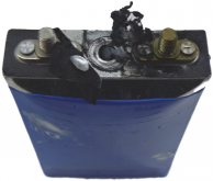
Picture of the 8ah battery after the short circuit test.

1609872802698.png

Their description of the event was interesting-
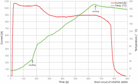
After 650 second mark, the battery safety vent
activated and released an intense stream of white colored
gas cloud from inside the battery (Fig. 14). It has to be
stated that vented gasses from a LiFePO4 battery are vary
noxious (they are literally boiling and decomposing
electrolyte). Apart from normally expected gasses created
during combustion of organic materials, such as CO2, CO,
H2, CH4, C2H4, C2H6, C3H6, C2H5F1 and others, other
toxic compounds like HF (hydrogen fluoride) and POF3
(phosphorous oxyfluoride) are present, derived from fluorine
used as lithium battery electrolyte [26].

The tested LiFePO4 batteries demonstrated very good parameters
regarding the safety of operation. The neither exploded, nor
ignited and thus did not created a danger for human life and
health (Fig. 16). The plates of 160Ah LiFePO4 battery did
not ignite even when exposed to open flames

It should be noted that their open flame test was on just the plate after the short circuit event. I believe the vapors emitted during the short circuit event can be flammable under the right circumstances. However, none of them ignited during the test.
 
Is that another way to state SCCR - in multiples of C?
The C rate is a way to refer to the current in relation to the capacity of the battery. So for the 160 amp hour battery, a 1C draw would be 160 amps, a 2C draw would be 320 amps. For the 8 amp hour battery, a 1C draw would be 8 amps. It is an easier way to evaluate the capabilities of batteries in comparison to one another if their capacities are different.
 
Last edited:
So this guy has this what to me is an enormous battery bank and says the SCCR is well over 20,000A. The question I have is if that is dependant on the size of the bank. It looked like several batteries hooked together - let's suppose parallel - would one battery alone have the same SCCR? At the moment I have one 100Ah / 12V lithium that I'm hoping to get the SCCR for. Nice battery and I expect to get another in the coming months and daze. Would that change the SCCR?

I think if you know the short circuit current and internal resistance for the individual cells or the assembled battery, you could draw up the circuit on paper to determine IR and short circuit current of the system. I haven't done this, but imagine that's how it would be done, short of actually measuring :oops:
 
Research Gate had a paper from 2017 that is available for download where they shorted a 160ah and an 8ah LiFePO4 battery.

https://www.researchgate.net/public...tudies_of_Batteries_used_in_Electric_Vehicles


It looks like the current peaked at about 7C for the 160ah and about 10.5C for the 8ah battery.
That seems like extremely low short circuit current for the batteries?
Maybe test rig was the limiting factor?

Internal resistance of typical 160 Ah lifepo4 would suggest LOT higher currents even if there is some other limiting factor like chemical reaction speed inside the battery.
 
I am building a LiFePO4 battery bank for my vehicle using 8x EVE 105Ah cells in a 2p4s configuration (12V, 210Ah). While not an EE, I am fairly comfortable with circuit design and protection. My question pertains to main circuit protection, specifically short circuit protection.

I see a lot of diagrams using something like a ANL, AMI or even MEGA type fuse for main circuit protection. Problem is those only have a max interrupt rating of 6000A/5000A/2000A respectively. While I could not find the short circuit current specification specific to my cells, I understand it could be greater than 6000A.

So the question I have is how are folks justifying the use of these fuse types for LiFePO4 battery bank main circuit protection? Especially battery banks larger than mine? Is the current rate of rise expected to be low enough so a lower rated fuse can clear?

The standard fuse I would expect to see in this application is the class T which is rated for 20kAIC, however I am not convinced that would necessary for my situation and am having a hard time justifying the high cost. I am considering using a MRBF fuse instead which is rated for 10kAIC in a Blue Sea 5196 fuse block. Any concerns with this or should I just use the class T?

Thoughts? TIA.

Looking from manufacturer specified graphs it looks like one cell would have:
3.30v @0.33C discharge (0.33*105=35A
3.07v @ 3C discharge (3*105=315A)

extrapolating to dead short and 0 volts (dI/dU) we get 280A/0,23V = 1217A short circuit current per cell.
2 cells in parallel would be ~2400A.
Note: connecting more cells in series doesn't increase the maximum short circuit current as you add also more resistance every time.
Real-world "short-circuit" current often increases with series connection as the cabling might be the actual limiting factor. But it is always below the maximum short circuit current in any case.

LiFepo4 seem to have rather small short circuit current compared to something like power-optimized Li-Po.
But that is what makes it safer...
(5Ah Li-Po is capable of 2000A short circuit current.)

extrapolating to larger systems 6000A breaking capacity ANL fuse would be ok up to 600Ah LiFePo4.
And lot less with some other lithium chemistries.
 
I am building a LiFePO4 battery bank for my vehicle using 8x EVE 105Ah cells in a 2p4s configuration (12V, 210Ah). While not an EE, I am fairly comfortable with circuit design and protection. My question pertains to main circuit protection, specifically short circuit protection.

I see a lot of diagrams using something like a ANL, AMI or even MEGA type fuse for main circuit protection. Problem is those only have a max interrupt rating of 6000A/5000A/2000A respectively. While I could not find the short circuit current specification specific to my cells, I understand it could be greater than 6000A.

So the question I have is how are folks justifying the use of these fuse types for LiFePO4 battery bank main circuit protection? Especially battery banks larger than mine? Is the current rate of rise expected to be low enough so a lower rated fuse can clear?

The standard fuse I would expect to see in this application is the class T which is rated for 20kAIC, however I am not convinced that would necessary for my situation and am having a hard time justifying the high cost. I am considering using a MRBF fuse instead which is rated for 10kAIC in a Blue Sea 5196 fuse block. Any concerns with this or should I just use the class T?

Thoughts? TIA.
I've more or less given up trying to get the actual SCCR for my battery. It's been suggested to me that the battery BMS might be built to limit the SCCR regardless of what one might calculate - but who really nose? My inverter mfg wants me to use a Class-T but when I quiz them closely they concede that the MRBF will be okay. Sounds like we're chasing the same bunny around the same bush. I'm going with the MRBF.
 
That seems like extremely low short circuit current for the batteries?
Maybe test rig was the limiting factor?
I agree. I had also considered that testing one cell in isolation at 3.2 volts, the resistance of any poor connections will have a larger impact on the short circuit current than if you had cells in series for 12, 24, or 48 volts.

I was trying to find actual experiments or studies, so that we could see measured values. I did come across unsupported statements in various places that said short circuit currents for LiFePO4 were 20C to 30C. So based on the experimental data I found, those statements would make sense if someone took the experimental data and gave it a safety factor of 2.
 
Voltage is a huge factor here. The higher the voltage, the higher the chance of unintentional arc'ing. So while the fuse might be fine to interrupt 10kA at 12v, it might not be at 48v (not to mention you'll have more amperage on a short circuit of an LFP bank at 48 than at 12). And while this guy's test proved OK, it might not be OK 100% of the time. You don't want to be the 1% guy whose fuse fails to function properly and burns your house/RV/boat down. Personally I would never use MRBF as a main fuse for LFP, especially in a 48v configuration.

And as others have noted, the rig itself can be a factor -- it depends on the size of the wire exiting the fuse holder (and the wire involved in the rest of the short circuit). Personally, I'm going to assume a very large crescent wrench is providing the short circuit :)

I moved to a DC 250 amp circuit breaker because I blew two 300 amp class t's (80 bux) with inverter inrush current. The breaker was ~$90 and is rated 50kA. And now I also have a nice battery switch.

I could use more information on this, because I don't understand the inadequacy of an MRBF.

Regarding your last paragraph, how did a 250 amp circuit breaker work when a 300 amp fuse didn't? I'm using a Class T fuse, so I'm interested.
 
I could use more information on this, because I don't understand the inadequacy of an MRBF.

Regarding your last paragraph, how did a 250 amp circuit breaker work when a 300 amp fuse didn't? I'm using a Class T fuse, so I'm interested.

Oh, sorry yeah I left the explanation out of the fuse vs breaker. I could have stuck with the fuse because I now manually precharge the inverter capacitors. But I grew tired of the cost of replacing the fuses and went with a breaker which also gave me the ability to turn off the battery (including the BMS). Incidentally that breaker has a longer trip time so it doesn't trip even if I don't precharge. The Class T fuse was fast-acting (vs. slow-blow).

As for the MRBF problem -- the reason it has a lower interrupt rating than class T is because of the way the fuse blows. The metal that makes up the interior of the fuse melts and deposits in various locations inside the fuse. In a high-current situation, it's possible these molten pieces don't end up breaking the circuit because they fall too close to each other and the current doesn't get interrupted -- it arcs across the various bits of melted fuse. And the higher the voltage, the more likely that is to happen. A class T fuse "explodes" internally so this sort of failure can't really happen.
 
Voltage is a huge factor here. The higher the voltage, the higher the chance of unintentional arc'ing. So while the fuse might be fine to interrupt 10kA at 12v, it might not be at 48v (not to mention you'll have more amperage on a short circuit of an LFP bank at 48 than at 12). And while this guy's test proved OK, it might not be OK 100% of the time. You don't want to be the 1% guy whose fuse fails to function properly and burns your house/RV/boat down. Personally I would never use MRBF as a main fuse for LFP, especially in a 48v configuration.

And as others have noted, the rig itself can be a factor -- it depends on the size of the wire exiting the fuse holder (and the wire involved in the rest of the short circuit). Personally, I'm going to assume a very large crescent wrench is providing the short circuit :)

I moved to a DC 250 amp circuit breaker because I blew two 300 amp class t's (80 bux) with inverter inrush current. The breaker was ~$90 and is rated 50kA. And now I also have a nice battery switch.
Almost anything works at 12 volts, 48 volts gets lot harder to extinguish the arc.

Ever try to weld with large 12v battery? Really hard or impossible to keep the arc going no matter what amps you have.

Maybe also worth mentioning that not all ANL fuses are same. Renogy for example specifies only 180A ! breaking capacity for 20A ANL fuse

Indeed. But who knows how close these metal fragments can be inside the fuse.

Note that we're talking about MRBF not ANL. ANL is even worse for AIC ratings.
 

diy solar

diy solar
Back
Top