diy solar

diy solar

On Keeping LFP Warm

OK, so I got the first round of testing done. This is a quick update, when I get the data collected I will present it in a more organized fashion. I used a chest freezer at 0°F. I repeated the test using three different 100ah non-heated lifepo4 batteries, to get an average. The results were nearly identical, so for the sake of time I will just use one going forward. For consistency, all batteries were charged completely at room temperature @ .2C and placed in the freezer for 12 hours before the discharge test began. I have a few preliminary thoughts:
1. The batteries warmed up *much* faster than I thought they would at .25C discharge.
2. I assumed the charge inhibit function would allow a very small charge in, even at freezing temperatures, this was not the case. I had to move the battery into the refrigerator overnight and warm it up to 38°F. I charged the battery at .25C, it warmed up much less than it did when it was discharged in the freezer.
3. I will use my IR camera next time to determine if the heat is coming from the cells or the BMS, and attach those images to the final report.
4. I also tried identical testing with a brand new AGM battery. I was expecting a severe reduction in power... not true. It did produce less, but considering it was at 0°F, it held up surprisingly well.
5. This is a lot more time-consuming than I originally thought. I do not have any data logging equipment, I'm doing it the old-fashioned way with a notebook and pen. It will take a few weeks or more to complete the testing. The internet is full of theory and assumptions. I'm looking forward to getting some real-world results together to serve as a reference. Stay tuned.
 
1. The batteries warmed up *much* faster than I thought they would at .25C discharge.
I guess I would have thought the same as you: That a bigger current would be required to actually warm the cells.
2. I assumed the charge inhibit function would allow a very small charge in, even at freezing temperatures, this was not the case. I had to move the battery into the refrigerator overnight and warm it up to 38°F. I charged the battery at .25C, it warmed up much less than it did when it was discharged in the freezer.
That's a tribute to your BMS and it's low-temp cut-off. What BMS do you use? Does it allow you to set the low temp?
5. This is a lot more time-consuming than I originally thought. I do not have any data logging equipment, I'm doing it the old-fashioned way with a notebook and pen. It will take a few weeks or more to complete the testing. The internet is full of theory and assumptions. I'm looking forward to getting some real-world results together to serve as a reference. Stay tuned.
All I'm working with is "theory and assumptions" so you are doing us a service. Thank you @Bill Taylor !
 
still reading the whole thread but thought this might fit for support https://www.lairdthermal.com/thermal-wizard/thermal-wizard-enclosure-calculator
That looks pretty interesting. I plugged in my numbers, except for the thermal conductivity, which I would think is just the inverse of the R-value, thermal resistance. But that doesn't seem to work, as it makes the loss in my hypothetical numbers I posted earlier much higher than I calculated. I need to look through the info on the site. Thank you @curiouscarbon for posting it.
 
Update #2: I find myself repeating some tests several times. The results I am getting are in contradiction to my previously held assumptions and beliefs. I am using the same batteries, the same charging conditions, the same discharge machines. And I get the same results every time. This forum, and the internet in general, is full of speculation about how batteries work. There is a serious lack of unbiased information based on real-world test results. I am beginning to believe that almost everyone misunderstands how batteries work and just repeats what everybody else says. For example, it's common knowledge lead acid batteries lose most of their power when they get cold, right? Especially below 0°F. Not true. I tested three different AGM batteries, three times each. The average capacity loss at 0°F, compared to 70%, was 27%. That is a lot better than I expected. Also, Lifepo4 batteries warmed up quite nicely under moderate load. I tried four different 100ah batteries, their rise ranged from 8° to 16°F in just 15 minutes. This was with no enclosure or insulation of any kind, in a freezer at 0°F the entire time. I can't find where anyone has ever tested this before. I wonder if it's really necessary for people to build insulated boxes and heaters, when they could just have a small load on for a few minutes to warm the battery up enough to take a charge. But that all depends on how cold the battery is to start with, of course.
I thought this journey would take a few days. I can see now it's going to take quite a while. I'm continuing to collect information, I will post results as they come in.
 
For example, it's common knowledge lead acid batteries lose most of their power when they get cold, right? Especially below 0°F. Not true. I tested three different AGM batteries, three times each. The average capacity loss at 0°F, compared to 70%, was 27%.
I think that is pretty close to what I've read elsewhere, like at Battery University. Lead-acid batteries temporarily lose capacity when it is really cold, and regain it when it gets back up to 25°C. High temps cause permanent loss. I did some searching just now, and it seems most of the data I could find is about flooded batteries, rather than AGMs. However, I think the cold weather effects should be pretty similar.
That is a lot better than I expected. Also, Lifepo4 batteries warmed up quite nicely under moderate load. I tried four different 100ah batteries, their rise ranged from 8° to 16°F in just 15 minutes. This was with no enclosure or insulation of any kind, in a freezer at 0°F the entire time. I can't find where anyone has ever tested this before. I wonder if it's really necessary for people to build insulated boxes and heaters, when they could just have a small load on for a few minutes to warm the battery up enough to take a charge. But that all depends on how cold the battery is to start with, of course.
That is pretty fascinating. When you say a "moderate load" - Do you know what C rate you were using? I've been doing some discharge testing in my unheated garage. My focus was not on temperature changes, but I have felt the cells and could not tell any change. Next time I do it I will get out my digital IR gun and check for sure.

When you've seen the temp of the cells go from 8°F to 16°F, were they still in the freezer? If the freezer was at 0°F and the cells were 8°F, that probably means that the surface of the cells were 8°F, and the internal volume of the cells was probably warmer. Obviously there's no way to tell for sure.

I think the use case for many people may fit with your idea of just a periodic "moderate load" may be enough. However, depending on just how cold it is and just how often the cells need to be warmed, it may not work.

For my cabin, I would expect the ambient temps could be well below zero (I've got a temp logger up there for the winter, so I should know for sure once we can get up there). So my issue is how we handle an LFP battery when the cabin is unoccupied for 5 months or so. If we have to carry them out for the winter, that could be a deal-breaker, and I may be stuck with AGM. In this case I'm not sure a small load periodically is an option.

Great stuff though @Bill Taylor and I hope you can give us some C rates.
 
One of the batteries went up 8°F, another one went up to 16°F. All of them were kept in the freezer the entire time discharge rate was .25C (25 amps).
 
One of the batteries went up 8°F, another one went up to 16°F. All of them were kept in the freezer the entire time discharge rate was .25C (25 amps).
Ahhh. I read your post too quickly. So it sounds like you are pretty confident the cells were actually at 0°F when you started. Thanks for clarifying.
 
Bill,
Thanks a lot for your work. I'm also looking to "store" LiFePO4 batteries in a cold camper in the Adirondacks. My solar charge is sporadic with the snow, clouds, and generally the low solar during the winter. I was considering using the 24VDC direct solar feed (before the controller) to dump the solar heat to the batteries. IF they warmed up, the heater would shut down, feeding the full wattage of the panels to the controller and charging the batteries.

Was your internal temp sensor in between the cells in the pack, or possibly near the BMS or ambient inside air? Did you cover the sensor to insulate it from air to only read the cell surface temps?

I was concerned about using the battery's power to heat itself. If the sun was only available for a short time, then gone, it could deplete the battery by heating itself with no charging obtained from solar. Figuring .25C discharge on a 100AH battery, I could get 4 hours before the battery dies and shuts down the BMS. If I can heat the battery in 30 minutes, I get about 8 days(30 minute warmups) with no solar charge. Once the BMS shuts down due to low voltage, there could be issues with the solar controller due to the warnings (Never disconnect the battery without disconnecting the solar first).

I'd be interested in using the battery charge to heat itself with say a 30W heating pad on the bottom. I think your current 25A, 12V or 300W would be too hot for this test. .025C discharge of 30W would heat from the bottom, with some internal heating of the cells.

Is it possible to test this to get the temperature rise for different time periods? Given the dT curve, others could extrapolate startup at any temperature. Other guestimates will be necessary as your test setup would be uninsulated, any additional insulation would preserve the heat inside.

My 800W of solar panels will peak out at 80W ( for only one hour) in the winter. That's not everyday, but one out of 4 days. Usually the clear days run together, followed by days of clouds/snow. If I can self heat the battery with it's own power at .025C discharge (30W), I could theoretically switch the heater on with solar voltage, using the battery to heat itself quicker. .025C on the 100Ah would be 80 days at 30 minute warmups.

I'm new to LifePO4, and just bought one Big Battery 170Ah. I'm hoping to work a heating scheme without opening it for testing and voiding the warranty.

Thanks
Carl
 
The testing continues.... I would like to do at least 6 or 8 charge-discharge cycles with each battery to average out anomalies and get good numbers. I do not have data logging equipment, I am keeping everything handwritten on a clipboard. I'm looking for an easy way to plot that information on a graph, I may just draw it by hand if I have to.
The temperature sensor was placed on top of the cells covered in heat sink compound, below the BMS.
Good idea, I will do a few tests @ .1C and .05C, and a few with each battery wrapped in fiberglass insulation inside a styrofoam cooler, just to get a comparison.
I grossly underestimated the amount of time and effort involved in this venture. But due to the glaring absence of reliable information about this topic online, I feel compelled to see it through. I have learned more about lithium cells, BMS boards, and charging techniques than I thought I would. I can't wait to get everything together, so I can sit back and watch everyone argue and nitpick over it. (Only slightly kidding)
Bill,

Maybe a video camera watching a temp sensor and a clock? Speed it up and put it on the web. Let anyone watch/record their own data points. I don't expect a perfect curve drawn. You could probably write down the temperature and time for the first maybe 30 to 45 minutes, then maybe come back to it when it's stopped moving. The curve could be drawn by hand.

I don't know where the BMS is located in your battery. Do you think it's heating your sensor, or you are further away from it.

Each battery is different. The BigBattery is a metal case with the cells laying horizonal. The BMS is in a different metal compartment on the top. Will has shown that they don't touch the cells with their temp sensor. This could end up with quite different temperatures between the air and the real cells.

I have my Big Battery outside at 16F(-9C) now. I just started the generator and it didn't put any charge into the battery. That's a good sign, or I don't have it hooked up correctly.... I'll try it over the the next week to see when the BMS lets it start charging. It's still a complex thermal issue as the batteries are in a different metal section. I could heat the batteries, and never warm the temp sensor, or visa versa. Probably the best for me is to insulate the entire battery with a heater near the cells. I could use your estimated time period as a delay to soak the entire battery at temp for xxx minutes.

I just noticed my Victron Solar Charger uses the battery temp sensor to inhibit cold charging. The Big Battery uses the quick disconnect plugs, There is no easy way for me to put the temp sensor on the battery post, directly reading cell temps. I may have to change the charger inhibit temp, or create a thermal mass mockup to put inside the battery box insulation. This issue is probably the same for all LiFePo4 batteries. Any temp sensor you put on the battery terminal is nowhere near the cells. It's just a small terminal connected with wires through the BMS. It could be way off from the cell temps.

You can probably work out a few rules of thumb, ie "The Taylor Principles". A 30 lb 100 AH Lithium battery in a 1" foam box, will reach cell core temp of 10 degrees above ambient with a .05C discharge in 20 minutes. 20 degrees in 30 minutes, 30 degrees in 50... Just discharge the battery into a heater at that load for the proper time and you should be fine. No one will survey their own batteries to prove their thermal issues. Manufacturers will not care that the terminal temperature, or the BMS sensor isn't reading correctly. They get to sell another battery if you damage this one with cold charging.

Carl
 
I have a battery in the freezer now. I will start the .1 C test tomorrow. The temp sensor is maybe an inch below the BMS. I'm taking IR images with a FLIR, it doesn't look like the BMS is heating up as much as I thought it would. I will put a few of those pictures up. After I do a few of the lower rate discharge tests, I will duplicate them with the batteries insulated. It should make a nice addition..
I have been working with Lifepo4's and using them in my shop and RV for years. But since I started doing this testing, I've been writing everything down, taking notes and really paying attention. I have exchanged phone calls and emails with business and industry contacts, and learned more in the last few weeks than I have in the last 5 years.
I'm also finding out a lot about charging those batteries. A lot of my misconceptions about proper charging are being revised, as I am doing as much charging as I am discharging.
I'm looking forward to condensing everything down to a simple presentation. It's been enlightening so far
 
I grossly underestimated the amount of time and effort involved in this venture. But due to the glaring absence of reliable information about this topic online, I feel compelled to see it through. I have learned more about lithium cells, BMS boards, and charging techniques than I thought I would. I can't wait to get everything together, so I can sit back and watch everyone argue and nitpick over it. (Only slightly kidding)
Hi Bill, First, thanks so much for contributing all the excellent content to this thread. I'm really enjoying the process of learning about how these cells work, and all the systems that go into keeping them happy. I wanted to address your comment about the amount of time and effort involved in the studies you're conducting. Just a couple months ago, I purchased my first Arduino (a MKR1000), and I'm constantly amazed at how much you can do with them. For a project like yours, with a $5 microcontroller, and a couple bucks in components (NTC thermistors, wires, etc.), you could be monitoring and logging temps, voltages, and other attributes real time. I had never done any coding before getting an arduino, and it does take a bit of self-study, but it's pretty straight forward. I'd be happy to help you with the setup if you're interested.

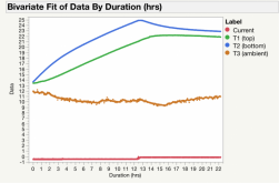
As an example of what you can do with a pretty simple set-up, here's some data I logged last night during a study of my cell warming setup. This is basically a test performed at 20watts for the first 12 hrs, followed by 5 watts of heat for the remainder of the test. I'm heating a 48V bank of 272Ah cells. A bit more detail about the setup I'm developing can be found here. I'll try to post some more info on these test results once I've had a chance to play with the data.

Temp Data (raw).png
 
Hi Bill, First, thanks so much for contributing all the excellent content to this thread. I'm really enjoying the process of learning about how these cells work, and all the systems that go into keeping them happy. I wanted to address your comment about the amount of time and effort involved in the studies you're conducting. Just a couple months ago, I purchased my first Arduino (a MKR1000), and I'm constantly amazed at how much you can do with them. For a project like yours, with a $5 microcontroller, and a couple bucks in components (NTC thermistors, wires, etc.), you could be monitoring and logging temps, voltages, and other attributes real time. I had never done any coding before getting an arduino, and it does take a bit of self-study, but it's pretty straight forward. I'd be happy to help you with the setup if you're interested.

As an example of what you can do with a pretty simple set-up, here's some data I logged last night during a study of my cell warming setup. This is basically a test performed at 20watts for the first 12 hrs, followed by 5 watts of heat for the remainder of the test. I'm heating a 48V bank of 272Ah cells. A bit more detail about the setup I'm developing can be found here. I'll try to post some more info on these test results once I've had a chance to play with the data.

View attachment 37803
First off - I agree in thanking @Bill Taylor for the hard work he is putting in to contribute to the greater knowledge about how these cells warm during discharge. I didn't account for that at all in the computations I supplied at the beginning of this thread.

Re: Arduino for logging, I am considering putting something together myself. I was thinking about using an ESP32s or ESP8266, and coding via the Arduino IDE. Did you add an SD card to your Arduino to store the logs? I have a breadboard ESP8266 collecting outside temps and sending them via HTTP Wi-Fi to a server I have in the house. I could probably use that same design (and most of the same code) to log the temps of LFP cells.

I've also been thinking about doing another microcontroller up at our cabin to log the Ah going in and out of the battery bank over time. One of the issues I have in considering a migration from AGM to LFP is that I don't think we really know what our energy consumption is over time. My wife and I go up there way less than either my brother's family or my sister's family, so it's hard to know how the system is really doing with no one there observing it. I'd need to think through reading the voltage divider data from a shunt, and I'd need to buy a SD card add-on, which should be easy.
 
Hi Bill, First, thanks so much for contributing all the excellent content to this thread. I'm really enjoying the process of learning about how these cells work, and all the systems that go into keeping them happy. I wanted to address your comment about the amount of time and effort involved in the studies you're conducting. Just a couple months ago, I purchased my first Arduino (a MKR1000), and I'm constantly amazed at how much you can do with them. For a project like yours, with a $5 microcontroller, and a couple bucks in components (NTC thermistors, wires, etc.), you could be monitoring and logging temps, voltages, and other attributes real time. I had never done any coding before getting an arduino, and it does take a bit of self-study, but it's pretty straight forward. I'd be happy to help you with the setup if you're interested.

As an example of what you can do with a pretty simple set-up, here's some data I logged last night during a study of my cell warming setup. This is basically a test performed at 20watts for the first 12 hrs, followed by 5 watts of heat for the remainder of the test. I'm heating a 48V bank of 272Ah cells. A bit more detail about the setup I'm developing can be found here. I'll try to post some more info on these test results once I've had a chance to play with the data.

View attachment 37803
Nice! It would be great to set Will up with this. He's done so much for us. He's torn down every battery on the market, has a freezer, and runs this website. If he published thermal surveys of the batteries, Everyone could use them.

Your chart shows what I was concerned with. Let's just pick the one off the shelf sample battery 4 prismatic cells,100 Ah LiFePO4's. Most people can put a heat pad on the bottom, but the inside cell temps are not monitorable. Your graph shows bare cells, a difference of about 4(units?). If this was the sample 100Ah, you would see differences between the Bottom of the case, the center of the cell mass, top of the cell mass, BMS temperature, and the temperature of the positive post/lug. This delay (15 hours) on your chart could be used for everyone that has that battery. You only need to do it once.

There would need to be a standard heater plate, insulation box, etc for all to judge their setup to see how it compares to the standard.

Unattended testing/results makes it easy. Put the battery in a insulated box in the freezer until all temperatures are steady state near the freezer temp. When this occurs, turn on the heater and graph dT. This would be external heating alone profile. Return to steady state cold, then draw a constant current out of the battery while heating with the controlled heater. This would be the internal with external heating profile. The last standard test would just be room temperature warming. Freeze the battery and pull it out of the freezer to a room temp. No insulation, no current draw, no heaters

There will be some "good/safe" amount of heating that most batteries can take. I hope it's more than what you are using. 15 hours to have the top of the cells up about 13 units is a long time. I'm hoping to see less than an hour or so. Bill was seeing internal heating when discharging the cells. That could accelerate heating.

From what Will has exposed, most battery manufacturers don't put the temp sensor on the center of the cells. They don't even make a temp sensor that works, or adjust it so low that it is worthless. This is financial engineering. They don't want people complaining that they can't charge the batteries. They turn on the heat for a day and the batteries still don't charge - They're broken" Those reviews kill a manufacturer. Silently destroying the cells with lithium plating is slow and the owners won't complain as much. Heck, they won't package up the LiFePO's to ship them back when they stop. They will just buy new ones.

Victron has temperature sensors that bolt to the battery positive. The solar chargers inhibit cold charging. This is not the cell temperature. That positive lug is simply some wires leading from the BMS/ Cells. Room heating will heat that external lug quickly, way before the cells even see warmth through the case. It appears Victron and the battery manufacture are doing great engineering, but this may be useless in saving your batteries.

I'm using Solar to attempt to charge my batteries in the winter, just to keep them ready for unattended loads when the sun is out. Solar is only a few hours in the winter. Heating should be enough to heat from -30F to +32F (delta 62F). Hopefully its warmed before the sun goes down. It may take a couple of days of heating to finally get the batteries warm. Each night, the insulation should save some heat from the previous day. I'm hoping I can use the batteries current, dumping into bottom heaters when the sun hits the panels in the AM. The amount of power at sun rise is low, but it could be a forecast of more sun to come that day. The battery has a chance of being recharged more than it used for heating.

I do believe heaters are the best for battery warming. Using ambient room heating will cause condensation on the battery. Having that cold block inside a camper in the winter will hit the dewpoint and accumulate a lot of water. Hopefully everything is conformal coated and can deal with operating while standing water is on the BMS.

Carl
 
Re: Arduino for logging, I am considering putting something together myself. I was thinking about using an ESP32s or ESP8266, and coding via the Arduino IDE. Did you add an SD card to your Arduino to store the logs? I have a breadboard ESP8266 collecting outside temps and sending them via HTTP Wi-Fi to a server I have in the house. I could probably use that same design (and most of the same code) to log the temps of LFP cells.
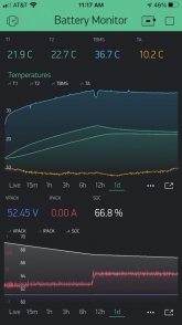
For the current iteration, I'm using an ESP32 (Node32s from Elegoo). I'm monitoring over Wifi via the Blynk app, which I believe is free. At any time, you can export the data to .csv for processing. If you're ok with 1 min logging interval, Blynk will save months worth of data on their server. Screengrab of the blynk app with everything I'm currently monitoring is shown below.

I should note that this latest iteration is actually taking data from the BMS (with the exception of the ambient temp sensor, which is just an NTC thermistor wired through one of the analog ports. One caution on the ESP8266: there's only one analog input, so if you want multiple analog sensors, you'll need a multiplexor.
IMG_481ED4609221-1.jpeg
 
Your graph shows bare cells, a difference of about 4(units?). If this was the sample 100Ah, you would see differences between the Bottom of the case, the center of the cell mass, top of the cell mass, BMS temperature, and the temperature of the positive post/lug. This delay (15 hours) on your chart could be used for everyone that has that battery. You only need to do it once.
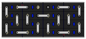
Sorry for the lack of units. All my temps are in deg C. The two BMS thermistors are sandwiched between the outer and inner rows of cells, T1 is between the top two cells on the left, T2 is between the bottom 2 cells on the right (shown in pic below).

I agree that 15hrs is a long time to get the cells up to temp. The temperature gradient from bottom (where the heaters are) to the top is my biggest concern with this setup, which is why I'm keeping the total wattage pretty low. I have a total heating capacity (at 100% duty cycle) of 100 watts. At that level, it should take ~3 hrs to get the cells up 10C, but I have no doubt that my temperature gradient would be unnacceptable at that level of heat (ie, bottom cells above recommended operating temp of 35C). For my situation, I think it's probably better for me just to try to keep them above freezing. It's looking like I can maintain a delta-T of 10C with about 4 - 5 watts of power. At that wattage, my difference between top and bottom cells is <1C, which seems fine. Considering that this bank is going into an insulated shop (normally unheated) with good solar gain, I'm thinking that the shop interior shouldn't go much below 0C very often.

Screen Shot 2021-02-01 at 5.27.44 PM.png
 
For the current iteration, I'm using an ESP32 (Node32s from Elegoo). I'm monitoring over Wifi via the Blynk app, which I believe is free. At any time, you can export the data to .csv for processing. If you're ok with 1 min logging interval, Blynk will save months worth of data on their server. Screengrab of the blynk app with everything I'm currently monitoring is shown below.

I should note that this latest iteration is actually taking data from the BMS (with the exception of the ambient temp sensor, which is just an NTC thermistor wired through one of the analog ports. One caution on the ESP8266: there's only one analog input, so if you want multiple analog sensors, you'll need a multiplexor.
View attachment 37834
Yeah, I messed around with Blynk some. I don't remember what the free threshold was, but it seemed pretty easy to run out of free before you run out of things to do. In my particular application (cabin in the mountains), using Blynk in the cloud is probably a non-starter, as there is no Internet there except when somebody sets up a wi-fi hotspot. If I pursue this, it will probably have to be logging to an SD card.

I agree on the ESP8266 limitations. I've actually got a few spare ESP32 (nodemcu) controllers in a drawer. As I recall they don't cost much more than the 8266 and have much more capability. I think the ESP32 doesn't have as much library support yet, but that may not matter for this application.

My problem is it seems I have too many of these little projects. I probably need to move the little temperature thing I did from the breadboard to a soldered hobby board, since it's been 8 months since I put it in use. I just need more time!
 
Sorry for the lack of units. All my temps are in deg C. The two BMS thermistors are sandwiched between the outer and inner rows of cells, T1 is between the top two cells on the left, T2 is between the bottom 2 cells on the right (shown in pic below).

I agree that 15hrs is a long time to get the cells up to temp. The temperature gradient from bottom (where the heaters are) to the top is my biggest concern with this setup, which is why I'm keeping the total wattage pretty low. I have a total heating capacity (at 100% duty cycle) of 100 watts. At that level, it should take ~3 hrs to get the cells up 10C, but I have no doubt that my temperature gradient would be unnacceptable at that level of heat (ie, bottom cells above recommended operating temp of 35C). For my situation, I think it's probably better for me just to try to keep them above freezing. It's looking like I can maintain a delta-T of 10C with about 4 - 5 watts of power. At that wattage, my difference between top and bottom cells is <1C, which seems fine. Considering that this bank is going into an insulated shop (normally unheated) with good solar gain, I'm thinking that the shop interior shouldn't go much below 0C very often.

View attachment 37835
Are you using the battery for heater power, or an external power? Bill was showing around 8 to 16F temp rise in 15 minutes at .25C discharge. Internal cell and external heating could push things faster.

Heat loss (power) is relative to the temperature differential. Trying to keep batteries warm, 24/7, waiting for a sunny day is lost power. You are okay drawing from them cold, just can't charge them. In my case, I don't have days to charge them.

Testing will show if the heating time is able to be reduced. I'm guessing the heater would need to be limited with a controller/snap switch to avoid overheating (constant power, then constant temp)

BTW.
I just checked my Big Battery with Victron SCC and temp sensor. It was -3C and the solar was at 42V, 0 amps. The battery was outputting 3Watts. The SCC was inhibited from charging below 5C.

My battery temp sensor is on a spare lead battery sitting near the BigBattery. I'm just using the + post for a junction temporarily. I placed my hand on the lead battery + post (and temp sensor) for about 2 minutes. The Victron Shunt and SCC saw a rise from -3 C to 8C. Once it saw above 5C, the SCC started charging the system. The Big Battery LED voltage readout went to 14.2V. It was 12.3V or so before. The Shunt said 0 amps. The Solar was attempting to charge the battery, but the BMS stopped the charging. The solar only supplied the 3 Watts constant load, nothing went to charging the battery.

This proved the lack of real temperature reading by Victron could fool the system into charging the cells too cold. This also proves Big Battery is properly shutting off charging at -3C.

I can extrapolate from your chart, using 1/4 of the heat power (5W) into a 12V battery (4s), it would take 15 hours to rise 10C. Things what would be pro's is 4 cells would be less mass, more surface area exposed, etc.

Thanks for your information.

Carl
 
Are you using the battery for heater power, or an external power? Bill was showing around 8 to 16F temp rise in 15 minutes at .25C discharge. Internal cell and external heating could push things faster.
Yes, I'm using power from the battery as the supply for the heating pads. This is going into an off-grid setup, so no other option. At 20watts, I'm only pulling an average of 0.4A, or 0.0015C. I can't imagine I'm getting a significant amount of heat at that rate.

Heat loss (power) is relative to the temperature differential. Trying to keep batteries warm, 24/7, waiting for a sunny day is lost power. You are okay drawing from them cold, just can't charge them. In my case, I don't have days to charge them.
I'll have 3800watts of panels on the roof, and winters tend to be pretty sunny here (Wisconsin). If I'm pulling an average of 5 watts to keep them above 0C, that's 120 watt*hrs/day (right?). Even if I only get an hour of sun per week at 25% efficiency (3800 watts * 25% * 1hr = 950 watt*hrs), that's enough to make up for that 120 watt*hr/day draw for the full week. Do I have that right? I might be missing something.

I'm sure everyone's situation is different (ie, how cold will ambient will get, how much capacity you have, how much PV power you can generate), but it seems that for my situation, maintaining temp is the right way to go. Maybe I'll set my programing to allow them to get a bit colder at night, so they just have to warm up a little before the sun comes out.

Let me know if I'm missing something here.
 
Yeah, I messed around with Blynk some. I don't remember what the free threshold was, but it seemed pretty easy to run out of free before you run out of things to do. In my particular application (cabin in the mountains), using Blynk in the cloud is probably a non-starter, as there is no Internet there except when somebody sets up a wi-fi hotspot. If I pursue this, it will probably have to be logging to an SD card.

I agree on the ESP8266 limitations. I've actually got a few spare ESP32 (nodemcu) controllers in a drawer. As I recall they don't cost much more than the 8266 and have much more capability. I think the ESP32 doesn't have as much library support yet, but that may not matter for this application.

My problem is it seems I have too many of these little projects. I probably need to move the little temperature thing I did from the breadboard to a soldered hobby board, since it's been 8 months since I put it in use. I just need more time!
I think I paid $11 for the ESP32 boards I'm using (from HiLetgo, not Elegoo as previously noted). Pretty reasonable for what you get. The only down side I've found with the ESP32 board is that the ADC is not perfectly linear. For most applications, not a huge deal, but for monitoring voltage, I did have to run a 3-point calibration to get accurate readings.

I've got the same problem with internet access at the location where my setup will be going. There's reasonably good LTE cell service, so my plan is to get a hotspot. Need to look into how much power those things consume, and if there's any way to minimize consumption (eg, cycling them on/off). Bottom line is that having built this battery myself, I really don't trust it to run on it's own all winter. Really need to be able to monitor things to make sure everything's doing what its supposed to.
 
Thanks to everybody... I wonder how much we could get done if we were all in the same shop for a few days. Hmm. It makes me wonder why a team of four or five guys haven't spent a week in a lab doing this. You would think it has been done before, right?

I have thought about building a simple arduino based datalogger, but like Horsefly, I have too many irons in the fire right now. This old dog learns new tricks all the time, but my brain thinks analog. I am familiar with digital circuits but in school in the 80's I learned a lot more about vacuum tubes than 0's and 1's. ? I am always up for a challenge though, maybe if schroederjd could point me in the right direction, it would be a good summer project.

I agree completely with diyernh, temp sensor placement is important. If the battery is changing temperature rapidly, the corners of the cells will always be a different temperature than the center. If the battery was kept at a constant temperature those differences would dissappear, but this may not be practical for all applications. I wonder how much power it would take to keep a well-insulated battery at a constant temperature vs warming it once a week for the purpose of charging. Perhaps multiple temperature sensors would be better? What do you guys think? Are we splitting hairs?

Has anyone seen any data regarding cell efficiencies at different temperatures? This week I started discharging batteries in an insulated cooler to see how much difference it would make vs the battery being uninsulated. (I was assuming the battery would warm faster being insulated) I always start by charging the batteries completely at room temperature and they go in the freezer (0°F) around dinner time. By morning, battery temperature has always been 0°F. Well, because the battery was insulated, it only got down to 20°F by morning. I ran the test anyway, and this time, heat gain at .25C discharge was significantly less than it has been at 0°, despite being insulated. I would have to assume the batteries are more efficient when they are warmer, resulting in less heat being generated. That may be a fly in the ointment for my type of testing.

Also, there doesn't seem to be a linear correlation between discharge rate and heat gain. My numbers at .1C vs .25C don't seem to add up.

And while we are at it, what about charge rate? I always charge cold lifepo4's at a lower current. Should any temp monitoring/heating circuit incorporate an output signal to reduce charge rate below 50°F? Perhaps that is a topic for another thread.

Because of the time involved to bring the cells to room temperature, charging them, and then cooling them down to testing temperature, I can only discharge two per day. Sometimes it feels like I have fallen down the rabbit hole, but I believe if we collect enough data it will start to make sense.
 
Last edited:
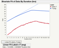
At the risk of over-posting on someone else's thread...I did some quick calculations using the data collected over the last 24 hrs. Below, I've plotted average pack temperature and delta-T (from ambient) over time (all in Deg C). From this data, I wanted to check two things:

1) How much energy does it take to raise the temperature of these cells? Horsefly, your original estimate was around 8.1 Wh per deg C for a 4-pack of 280Ah cells. Using the slope of my average temp curve from the first three hours of the test (when delta-T was at its lowest, and least significant), I get a value of 0.92 C/hr. Using my constant heating rate over that period, I get a heating requirement of 22 Wh/C. I'm heating 16 cells, so divide that by 4, and I get 5.4 Wh/C for a pack of 4 cells. Not too far off from your theoretical value!

2) What's the heat loss of my insulated box? I had originally used the Laird online calculator that others had referenced to determine how much heating power I was going to use. That gave me an estimate of 13watts to maintain a delta-t of 10C, or 1.3 W/C. I've now reached a steady state with constant heating at 5 watts. My average pack temp is 22.2C (21.6 on top, 22.8 on bottom). My average ambient temp over the past few hours is 11.0. So that's a delta-T of 11.2C from 5 watts, or 0.46 W/C. That's quite a bit different from the theoretical value, which I'm guessing is the result of 1) heat produced by the BMS, 2) heat produced from the batteries themselves, 3) addition insulation provided by the table its sitting on and the steel box?, 4) maybe something to do with a lack of convection, as my cells are up against the back and sides of the box.

Anyway, not that any of this really matters, but it is nice to have data come out at least close to where it theoretically should...

Temp Data (analysis).png
maye
 
I have thought about building a simple arduino based datalogger, but like Horsefly, I have too many irons in the fire right now. This old dog learns new tricks all the time, but my brain thinks analog. I am familiar with digital circuits but in school in the 80's I learned a lot more about vacuum tubes than 0's and 1's. ? I am always up for a challenge though, maybe if schroederjd could point me in the right direction, it would be a good summer project.
Happy to help in any way I can Bill (I got spare time...). If you send me a bit about what you want to measure, I can send you a simple circuit design (with purchasing recommendations) and the code (in Arduino IDE). Are you interested in monitoring by Wifi? Or are you ok having the monitor plugged into a PC during your testing?

I should note that I am FAR from an expert. I'm sure others will chime in on the best way to do things.
 

diy solar

diy solar
Back
Top