diy solar

diy solar

Trying to understand Low and High voltage disconnects

Al Slitter

Trying to learn something new every day!
Joined
Feb 22, 2021
Messages
85
Location
Thailand
I am trying to wrap my mind around this topic and hope by sharing my thoughts it will confirm or provide for something I have missed.

Using a cheap BMS versus an expensive one has obviously quality differences but in addition the cheaper BMS have preset upper and lower
voltage cut offs and the cannot be changed.
However with my solar controller (Tracer 4215bn ) I intend on using it to control the battery pack. The thoughts that I have about this is that the BMS works at the cell level while the solar controller works at the battery level, I hope that I have explained this well enough!
If I use conservative values for both disconnects at the controller level it will negate the preset values of the cheaper BMS?
My thoughts are setting the cut offs at 13.35Volts (3.375 Volts at the cell Level) on the high end and 12.8 Volts (3.2 volts at the cell level) on the low voltage disconnect based om a 12 Volt system.

Thoughts please.
 
Last edited:
I am trying to wrap my mind around this topic and hope by sharing my thoughts it will confirm or provide for something I have missed.

Using a cheap BMS versus an expensive one has obviously quality differences but in addition the cheaper BMS have preset upper and lower
voltage cut offs and the cannot be changed.
However with my solar controller (Tracer 4215bn ) I intend on using it to control the battery pack. The thoughts that I have about this is that the BMS works at the cell level while the solar controller works at the battery level, I hope that I have explained this well enough!
If I use conservative values for both disconnects at the controller level it will negate the preset values of the cheaper BMS?
My thoughts are setting the cut offs at 13.5 Volts (3.375 Volts at the cell Level) on the high end and 12 Volts (3 volts at the cell level) on the low voltage disconnect based om a 12 Volt system.

Thoughts please.
The only problem is that you will not have individual cell protection in the case of a runaway cell.
 
This is a new concept for me, what is a runaway cell issue. What is the physical aspects of this?
Why would a BMS not handle this?
If this is the case why even have a BMS?
 
This is a new concept for me, what is a runaway cell issue. What is the physical aspects of this?
Why would a BMS not handle this?
If this is the case why even have a BMS?
That is the whole idea of having a BMS. I was referencing to you not having a BMS. Sometimes when cells are not matched or a cell goes faulty it can lead to a 'runaway' cell , either on charge or discharge.It basically means that one cell reaches it OV ( over voltage ) or UV ( under voltage ) points before the others. Most cells ( depending on quality and age ) track well between 10 & 90% SOC , so you program the BMS to operate in this band.
 
Last edited:
Thank you for the clarification you did a very good job of explaining it.
However here is a a thought, if I set the high and low disconnects on the controller this will control the voltages outside of the prescribed range and that should led to a battery having a long life cycle?
Using a cheaper BMS will still have the cell parameters hard coded into the system so that should in some way help with the rubaway condition if it ever develops?
Yes , I agree. I am using a cheapy ( $10 on Amazon ) BMS in one of my portable packs. It comes with settings hard coded and so far it is working great. Cells track within 50mV of each other.
You can read my post here : https://diysolarforum.com/threads/tiny-bms-controlling-105ah-12v-pack.6893/
 
Not setting the charge profile high enough can lead to no cell balancing. A quality BMS allows you to change the threshold when cell balancing takes place. Say the default cell balancing threshold is 3.4v. If you charge to only 3.375v then cell balancing will never kick in. Maybe you never need it, but maybe you do. Either way, I wouldn't want to miss out on cell balancing.

I'm using the Victron defaults on my solar charge controllers, which I recall use an upper limit of 14.4v. In the future, I may set that to 14.0 during the winter. Should I do that, I will also adjust my BMS to commence cell balancing at a lower threshold. Then again, maybe I won't change a thing and just keep the defaults. Given the number of cycles I'm expecting to get out of my LiFePO4 cells, by the time they're five years old I'll probably have sold the trailer or I'll get the itch to go with the latest and greatest 1000Ah cells.
I am still in favor of a decent quality BMS which gives access to settings etc and allows you to adapt to certain conditions. My cheapy BMS is more for experimental purposes as I normally use the DGJBD BMS that I previously reviewed.
 
As a follow up query can some one explain to me the following on a BMS:

A common port versus a separate port
In addition please clarify the function of the P- and C- ports?
I assume that the P- is for Power and C- is for charging?

From a connection point of view for a solar shop 12V system one would connect the C- BMS connector
to the negative port on the Solar controller and the B+ BMS connector to the positive terminal on the battery then connect that
terminal to the positive port on the solar controller.
I hope this makes sense, I am just trying to wrap my head around the various configurations of what one can find on BMS's.
Thank you in advance.
 
I read the posts/links but they have not helped me understand my confusion.
 
From a connection point of view for a solar shop 12V system one would connect the C- BMS connector
to the negative port on the Solar controller and the B+ BMS connector to the positive terminal on the battery then connect that
terminal to the positive port on the solar controller.

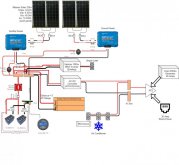
Connections are easier when a set of common bus bars are used. My connections are described like this:
Battery Negative -> B- BMS C- -> Shunt -> Negative Common Bus Bar
Battery Positive -> Fuse -> Battery Disconnect Switch -> Positive Common Bus Bar

All loads and charges are connected at the common bus bars. The portion of your post that I quoted above, that is underlined, is where my setup is different. The solar charge controller's positive lead simply goes to the positive bus bar.

The picture below is the wiring diagram of my system. Notice that everything connects at the (unlabeled) common bus bars that are above the red switch on the left.

SolarDesign.jpg
 
When properly operating, the BMS should not have to do anything. The charging source should stop at your desired maximum charge, and your loads should cut off at your desired lower limit. And both ends should be well inside of where the BMS would shut down. My BMS is fully programmable, and I have it set close to the limits for each cell. If everything is working fine, my NMC cells only charge to 57.2 volts or 4.086 volts per cell, the BMS would cut off at 4.18 per cell. So the balance would need to be off like 80 mv for the BMS to shut it down. On the discharge side, I left even more room. On day to day cycles, I only discharge down to 51.0 volts or 3.643 per cell, which is about 50% remaining. If I am off grid during a power failure, I have the shut down set to 46.2 volts or 3.3 volts per cell. The BMS does not cut off until 3.0 volts per cell. So the balance down there would need to be off by 300 mv. As long as the cells hold balance, the BMS is just along for the ride. If your BMS is just a resistor passive balance, you should make sure it does get into the activation area. I have the JK (HelTec) BMS with active balancing, and I have it balance any time the cells are above 3.2 volts, and the difference is over 6 mv. Even at that low threshold, it rarely ever triggers any balance current. My cells are all holding within 3 mv. My BMS will also shut down on high temp, low temp, and over current charge or discharge. All of those values are also adjustable. If your BMS is hard coded, be sure to stay in it's safe range and it should only ever trip if something is going wrong. If a cell or a connection is going bad, or an excessive load is drawing, the BMS is there to protect the cells. That should be it's only job. A BMS is not a charge controller.
 
First off thank you HRTKD you fully understood what I was saying and you answered my question so well that even I understand how the connections take place. The image with the bus bars simplifies everything at least for me, thank you again!
 
Thank you as well GXMnow, for your detailed description on the functining of a BMS. This parrallels my thoghts completely and shows that I am now on the right trck.
Thank you again!
 
Back
Top