


You are using an out of date browser. It may not display this or other websites correctly.
You should upgrade or use an alternative browser.
You should upgrade or use an alternative browser.
DALY BMS PC software connection issue
- Thread starter ttiburst
- Start date

Hello,
Me too!
My LiFePO4 cells finally arrived and I seem to have the same BMS as the OP. I connect using usb and can "see" the BMS using Sinowealth BMS program. I can see details of battery including voltages and current as I (slowly) charge it. I can't get any connection using the PCmaster program from Daly. Nor can I connect using BT.
The android app SMART BMS fails to see BMS BT. BTW I did try shorting out the two pins by the monitor plug as suggested on the forum.
I appreciate all the Daly related .pdf uploads and have read through them. None of them are what I would call decent user directions. How do you all figure this stuff out?
Farmgirl0527
New Member
- Joined
- Dec 29, 2019
- Messages
- 83
My daly Bluetooth works fine, but cannot get the pc to connect. Using the cable they sent me. Guess I'll have to bug the sales engineer.
Farmgirl0527
New Member
- Joined
- Dec 29, 2019
- Messages
- 83
Would u mind sendi,g a link to the driver
Would u mind sendi,g a link to the driver

Daly Sinowealth software
Ive uploaded the Daly Sinowealth tool (used for 3s-4s BMS). The Daly supplied USB-UART cable also needs a "CH340" driver which is also included. Some instructions on how to use it are here...
 diysolarforum.com
Just go to the resources section and type in "Daly" in the search.
Diysolar123
Solar Addict
- Joined
- Feb 28, 2021
- Messages
- 675
yep.. you MUST load up the Ch341 driver I believe.
as for the victron if you have that you need the pl2303 OLD driver...do not use the latest as the victrons tend to use clone chips and the latest prolific drivers will not work.
as for the victron if you have that you need the pl2303 OLD driver...do not use the latest as the victrons tend to use clone chips and the latest prolific drivers will not work.
达锂上位机下载 - 下载专区 - 达锂品牌官网-锂电池保护板厂家-东莞市达锂电子有限公司|DalyBms品牌官方网站
 www.dalyelec.com
Different versions depending on the model.
I had trouble establishing com to Daly 4S BMS using PCMaster from DalyBMSMonitorV1.1.6.
The CH340 driver insisted on installing as a port (COM12) that the PCMaster would not recognize.
(it wanted COM7 - already in use).
When the CH340 port was altered to suit the PCMaster, it was displayed in the PCMaster
comm select window as a second preferred port with the same name (two x COM7). Neither of these
ports worked.
I removed the CH340 driver and some how the next time the UART/USB dongle was inserted
into the PC, it's driver was 'automatically' installed. CH340 was registered as COM12 and
PCMaster now offered the COM12 connection, which worked to communicate with the
BMS to set, read and save .cfg files, and to record a log of monitor readings.
That's MY com issue resolved for now. Getting predictable function, every day, every time,
from the BMS without user intervention, is the next goal.
The BMS monitor PC comm function is not as secure on this 32bit WXP lab PC as you might like.
Its relevance to users of more current hardware may be doubtful, though the SW was first
developed to include the older environments.
The period of time that the BMS will continue to communicate with a PC UART/USB link is
uncertain. There is a 'BMS Life' indicator on the DalyBMS-V1.1.6 'Data Monitoring' tab, in
the PCMaster executable's window. This counts up to 255 in non-second increments while
communication is actually in effect. The 'BMS Life' count does not always increment by
single even units in the display, but may increase in larger increments irregularly, possibly
indicating comm issues. The count returns to zero and increments from there, continually.
When it stops, a log file is loaded into a Save Data folder in the executable's directory.
This .xlsx formatted file includes a timestamp that is incremented for each reading by one
or two seconds. I assume this is a reading of the PC's clock, averaged to the nearest second.
Examination of the log, comparing timestamps to 'BMS Life' increments, suggests that
one BMS increment is, on average, equal to one second. Discontinuity in the record
suggests that comm intervals are not as regular. A 255 count corresponds to ~4min15sec.
This rate of recording may not be suitable to long term monitoring, but may be capable
of recording relatively short transients in the BMS and battery system's operation, in
troubleshooting. Anything of shorter duration would probably need a multi-channel scope
with deep memory, to be accurately recorded.
The programming of BMS timeout values (15300 as recommended for 4S, in this case) does
not appear to be 'sticky', between isolated communication sessions, when separated by times
of PC or program non-operation. Other user-programmed values seem to survive. The value
is retained only so long as the current session continues, or does not cease functioning by
itself. Closing and opening the comm port, without closing the program, reveals that the
BMS Life count continues inside the BMS and is updated to current values in the PCMaster
DalyBMS-V1.1.6 'Data Monitoring' tab when the comm port is reopened.
Closing out the non-operating program and restarting it was sufficient to re-establish a
new comm session, providing that a >2A charging state was present, but in the process,
other comm software running on the machine, using other ports, was interrupted.
This may just have been a coincidence, but an Agilent Datalogger, running without issues
for some years, was one of the victims.
After a first comm session was lost some days ago, it was not re-established until
after a system file check was run on this XP installation.
Current work will involve trying to re-establish function of the datalogger, as it is used
as the primary reference for this battery system, while the BMS performance and behaviour
is being evaluated.
Last edited:
After the BMS stopped reporting, managed to get datalogger and BMS back upCurrent work will involve trying to re-establish function of the datalogger, as it is used
as the primary reference for this battery system, while the BMS performance and behaviour
is being evaluated.
and running. Put the BMS UART/USB interface into an 'enhanced' USB port this time.
The timestamps on the log and the corresponding 'BMS Life' ticks showed that, at the
time of lost comm on this last run, the comm was succeeding on only every 30th
possible BMS reporting interval. Total log entries 2276 over an interval of 5hrs37min.
I note that the PCMaster consumed most, if not all, of the PC's microprocessor's
resources on this machine, towards the end of the run. This is a simple Pentium4-2.8GHz.
At this time I'm introducing a USB isolating element in between the dongle and the
PC, to act as isolation and buffer, to remove ground bounce and signal integrity
from the equation.
Last edited:
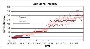
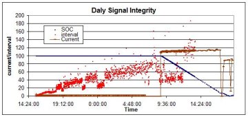
After a number of trials at quiescent ( 0 and 2A charging), charging (80-90A)
and discharging (100-120A) states, a pattern of Daly BMS to PC comms begins
to form.
These are illustrated in the two attached charts. Both show the time-stamped
'BMS Life' reporting intervals reported in the logs of the trial periods before
reporting either ceased entirely and/or the DalyBMSMonitor program crashed.
The reporting interval generally increases with time. In the 211125 plot, this
interval actually went off the scale of the graph (>200 BMS Life cycles),
reaching the 500-600 count.
As previously stated, the DalyBMSMonitor program uses a lot of this PC's
microprocessor's capacity. It starts at 20% and rises pretty quickly (<1hr)
to ~80%. If other programs running simultaneously are terminated, it can
rise further.
Another interesting point to note:
The log files carry a date-stamp that identifies the last recording time or log
entry.
Of the five logs present at the end of testing, 2 crashed within minutes of 3PM
and 3 crashed within minutes of 9PM.
This may reflect or amplify the relevance of reports of BMS units repeatedly
ceasing to function normally at a specific time of day.
This system install is located at GMT-5. and no equipment in the test bed has an
internet connection, or wireless comm. Clock times reported are those of the PC.
Reports of other users experiencing anomalies at certain times of day are
present on at least one other thread (8S, PV and bluetooth comms).
diysolarforum.com
[Beside the point; the logs developed by the DalyBMS-v1.1.6, in .xlsx have the SOC and
current column headers swapped over. I don't know if this reflects possible problems
in actual comm/BMS processing activity.]
and discharging (100-120A) states, a pattern of Daly BMS to PC comms begins
to form.
These are illustrated in the two attached charts. Both show the time-stamped
'BMS Life' reporting intervals reported in the logs of the trial periods before
reporting either ceased entirely and/or the DalyBMSMonitor program crashed.
The reporting interval generally increases with time. In the 211125 plot, this
interval actually went off the scale of the graph (>200 BMS Life cycles),
reaching the 500-600 count.
As previously stated, the DalyBMSMonitor program uses a lot of this PC's
microprocessor's capacity. It starts at 20% and rises pretty quickly (<1hr)
to ~80%. If other programs running simultaneously are terminated, it can
rise further.
Another interesting point to note:
The log files carry a date-stamp that identifies the last recording time or log
entry.
Of the five logs present at the end of testing, 2 crashed within minutes of 3PM
and 3 crashed within minutes of 9PM.
This may reflect or amplify the relevance of reports of BMS units repeatedly
ceasing to function normally at a specific time of day.
This system install is located at GMT-5. and no equipment in the test bed has an
internet connection, or wireless comm. Clock times reported are those of the PC.
Reports of other users experiencing anomalies at certain times of day are
present on at least one other thread (8S, PV and bluetooth comms).
Daly BMS - Bypass Low Battery Question
Good day. I have a Daly BMS on a 24V 202Ah LiFePo4 battery system. I am using a Victron 100/20 MPPT Solar Charger. Currently, the equipment and Charge Controller's Negative wires are connected straight to the Daly's "P-" Black cable and the Equipment and Charge Controller's Positive (Red) wires...
diysolarforum.com
[Beside the point; the logs developed by the DalyBMS-v1.1.6, in .xlsx have the SOC and
current column headers swapped over. I don't know if this reflects possible problems
in actual comm/BMS processing activity.]
Attachments
Last edited:
The comms responsibility was shifted to a W7 portable machine, using a
later rev of both the BMSMonitor (v1.2.5) and the driver installer, to see
if the stink followed the monitoring system, for this specific BMS.
The installation parked itself on Port7, the only USB port offered by
the newer BMSMonitor's GUI and the only one registered on the
new machine's device manager. For the life of me, I can't remember
whether the live BMS (still talking sporadically to the W2K port when
usb was pulled) required a charging current before it was first
read by the new W7 installation.
There was no time to do a long-term trial, but the new comms link didn't
exhibit degradation that was time dependent, nor did the monitoring
executable consume abnormal microprocessor resources. No freezes,
crashes or long comm time-outs were present. The only non-sticky
program values were those that read back with Chinese characters
- battery production date, battery type and battery operation mode.
SW version reported 20210729-1002A
HW version BMS-ST030-303E
The system hardware now has to be physically reconfigured for end use,
before this testing can proceed.
The physical transfer of the system had some glitches. (Be advised that a
monitoring harness, meticulously and perfectly installed backwards, will
kill a Daly BMS, even if each wire is individually fused.
Actual connection and wake-up issues with both the BMS (low-z switch)
and comm lines are dealt with separately, in a later post in this thread.
To the point with software connection issues:
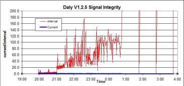
The new configuration, with a replacement BMS, connected to a newer W7
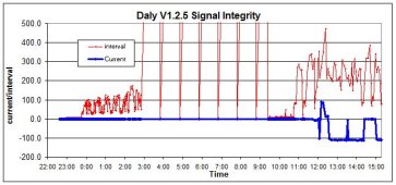
laptop and running updated monitoring SW (v1.2.5) eventually exhibited
the same kind of comms degradation as in the previous test situation.
With no charger or load connected (zero current), and just the comms program
reporting to the PC, logging intervals degraded, with the v1.2.5 program eventually
freezing and becoming unresponsive. The pattern of com intervals logged by the
program in the first significant long-time run is illustrated in the attached charts.
There are a few things to note about this pattern that argue against randomness:
- The jump in interval length at 2100hours corresponded to a sudden increase
in program use of microprocessor resources - from ~14% to 50%.
- a relative reduction in interval length occurred temporarily after 2249, when
the PC's internet connection was cut.
- Final comms are repeated successfully with low intervals at approximately
(exactly?) 1 hour intervals.
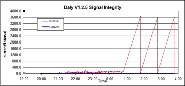
The final three hours suggest possibly intentional behavior that is undocumented
for this program. One might speculate that this is to save logging or other reporting
resources. Sleep timeout for the configuration remains set (and read back) at 15300sec,
in all trials. The effect of a sleep timeout on the log is not witnessed yet.
The unit and GUI were both unresponsive to to the keyboard 4hrs after the last log entry.
Communication was restored for later work only after hardware manipulation
recounted in the later post (below) reviewing the start-up and wake-up methods used.
When first connected, the monitoring program reported a cycle count of 2, which is
the first time this increment was witnessed running any version of the SW.
There was also odd information in the 'cumulative charge' and 'cumulative discharge'
settings - roughly twice that of the ratings of the system or the contents of these
'settings' in any previous trials with older HW and SW. Not something I'd noticed
and puzzling in that it showed up in new configuration. Not sure what it represents.
Was previously set manually at 112% of rating charge and 98% of rating discharge,
based on manual work experience with these cells.
SOC is reported at 50%, with the fully-charged cells, possibly as a starting point for
the new BMS.
monitoring harness, meticulously and perfectly installed backwards, will
kill a Daly BMS, even if each wire is individually fused.
Actual connection and wake-up issues with both the BMS (low-z switch)
and comm lines are dealt with separately, in a later post in this thread.
To the point with software connection issues:
The new configuration, with a replacement BMS, connected to a newer W7
laptop and running updated monitoring SW (v1.2.5) eventually exhibited
the same kind of comms degradation as in the previous test situation.
With no charger or load connected (zero current), and just the comms program
reporting to the PC, logging intervals degraded, with the v1.2.5 program eventually
freezing and becoming unresponsive. The pattern of com intervals logged by the
program in the first significant long-time run is illustrated in the attached charts.
There are a few things to note about this pattern that argue against randomness:
- The jump in interval length at 2100hours corresponded to a sudden increase
in program use of microprocessor resources - from ~14% to 50%.
- a relative reduction in interval length occurred temporarily after 2249, when
the PC's internet connection was cut.
- Final comms are repeated successfully with low intervals at approximately
(exactly?) 1 hour intervals.
The final three hours suggest possibly intentional behavior that is undocumented
for this program. One might speculate that this is to save logging or other reporting
resources. Sleep timeout for the configuration remains set (and read back) at 15300sec,
in all trials. The effect of a sleep timeout on the log is not witnessed yet.
The unit and GUI were both unresponsive to to the keyboard 4hrs after the last log entry.
Communication was restored for later work only after hardware manipulation
recounted in the later post (below) reviewing the start-up and wake-up methods used.
When first connected, the monitoring program reported a cycle count of 2, which is
the first time this increment was witnessed running any version of the SW.
There was also odd information in the 'cumulative charge' and 'cumulative discharge'
settings - roughly twice that of the ratings of the system or the contents of these
'settings' in any previous trials with older HW and SW. Not something I'd noticed
and puzzling in that it showed up in new configuration. Not sure what it represents.
Was previously set manually at 112% of rating charge and 98% of rating discharge,
based on manual work experience with these cells.
SOC is reported at 50%, with the fully-charged cells, possibly as a starting point for
the new BMS.
Attachments
Last edited:
When the BMS was first hooked up to the PC, without a charger or load, using v1.2.5
of the monitoring SW, it was not recognized as a port, until the thermistor was
removed and reinserted. Although the port was then visible to the program, no comms
were yet possible. The actual BMS power switch was LowZ.
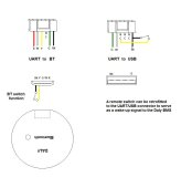
Swapping UART harness for a BT dongle and pressing the switch, then reinserting the
UART/USB harness showed that comms were available to the PC, with logging.
I examined the BT dongle and determined that the press switch was a simple mechanical
contact between two UART pins. A diagram is attached showing the relevant pin
functions.
There's no reason why the same switch cannot be installed in the USB harness, through
the addition of user-inserted wiring. This switch arrangement was proven to function just
as well, without interrupting UART/USB function. It's ability to 'stop' the BMS was not
demonstrated, though this seems to be hinted in SW control settings, as being intended.
It was used once or twice to restore low-interval comms and logging, albeit temporarily,
in longer trials, after the BMS had slipped into hourly reporting. This is illustrated in another
attachment. The log was not interrupted or restarted in this process, it just continued.
While in the hourly reporting mode, the BMS will not respond to settings read/write
panels. Toggling comm lines in the monitor window also has no effect on BMS reporting
behavior under those conditions, so the use of this switch to reset the monitoring reporting
intervals could prove useful, if the events triggering the slow behavior could be established.
The behavior of comms under charging and discharging conditions have yet to be
characterized, but I had a PC crash, shutting down cold, unattended during the
discharge phase. This W7 PC just doesn't do that, as a habit . . . . .
The PC comm interface GUI was confused at various stages of testing. Though the text
below the 'speedo' graphics remained functional, the graphics themselves would
dissapear, either individually, in bits and pieces, or altogether. Only program restarting
restored them.
MCU resource use starts out low and builds up gradually to ~50%, when the comms are
eratic. In hourly reporting mode, there is little or no MCU resource use.
of the monitoring SW, it was not recognized as a port, until the thermistor was
removed and reinserted. Although the port was then visible to the program, no comms
were yet possible. The actual BMS power switch was LowZ.
Swapping UART harness for a BT dongle and pressing the switch, then reinserting the
UART/USB harness showed that comms were available to the PC, with logging.
I examined the BT dongle and determined that the press switch was a simple mechanical
contact between two UART pins. A diagram is attached showing the relevant pin
functions.
There's no reason why the same switch cannot be installed in the USB harness, through
the addition of user-inserted wiring. This switch arrangement was proven to function just
as well, without interrupting UART/USB function. It's ability to 'stop' the BMS was not
demonstrated, though this seems to be hinted in SW control settings, as being intended.
It was used once or twice to restore low-interval comms and logging, albeit temporarily,
in longer trials, after the BMS had slipped into hourly reporting. This is illustrated in another
attachment. The log was not interrupted or restarted in this process, it just continued.
While in the hourly reporting mode, the BMS will not respond to settings read/write
panels. Toggling comm lines in the monitor window also has no effect on BMS reporting
behavior under those conditions, so the use of this switch to reset the monitoring reporting
intervals could prove useful, if the events triggering the slow behavior could be established.
The behavior of comms under charging and discharging conditions have yet to be
characterized, but I had a PC crash, shutting down cold, unattended during the
discharge phase. This W7 PC just doesn't do that, as a habit . . . . .
The PC comm interface GUI was confused at various stages of testing. Though the text
below the 'speedo' graphics remained functional, the graphics themselves would
dissapear, either individually, in bits and pieces, or altogether. Only program restarting
restored them.
MCU resource use starts out low and builds up gradually to ~50%, when the comms are
eratic. In hourly reporting mode, there is little or no MCU resource use.
Attachments
Last edited:
The use of the switch failed to restore more frequent comms in a slow-running
PC program instance, in succeeding trials. It WAS needed and proved capable
of starting a logging session on a newly connected BMS in all instances.
More accurate use of this feature would require knowledge of the BMS
controller's state machine and the requirements of the monitoring software.
The latter proved too unreliable and unpredictable to use as a continuous
system monitor. It does allow reprogramming of BMS settings, to account for
specific battery and system requirements, but may be required to check on
the integrity of configurations stored in the BMS, at a later date.
It did not seem to interfere with BMS function, once the BMS was woken up
and assumed control of the power train switch.
Using v1.2.8 of the monitoring software introduced no improvement
in long-term stability in communications by UART/USB.
In fact, it seemed that this rev could be counted on to reliably crash
the portable PC after about 2hrs of monitoring - leaving a log file
that never exceeded 255KB in size. This is a hard, unanticipated
power-down situation, though the W7 PC seemed unaffected on
any subsequent boot-up. The previous rev only did this once during
many hours of testing - normally being satisfied with just freezing its
own application environment.
I was also unable to establish bluetooth comms with the BMS using either
an emulator or an Android10 operating system (usb boot on portable PC),
due to emulator and OS inability to access PC USB hardware. A working
bluetooth interface would not detect the presence of the BMS.
I'll be installing the app on a regular smart phone or tablet in the near
future, in order to see it it might fly in the field.
Similar threads
- Replies
- 1
- Views
- 341
- Replies
- 0
- Views
- 286
- Replies
- 15
- Views
- 5K
- Replies
- 1
- Views
- 248