diy solar

diy solar

Relay/contactor question from a newbie

Solarfun4jim

Solar seduced :-)
Joined
Sep 22, 2019
Messages
743
Location
Sunny Scotland
Can a 240vAC(13A UK plug supply) circuit be switched using a continuous duty NO contactor with a 12vdc 0.8A 'control circuit' and rated at say 400A on the load side.
If not, why not exactly? If it is simply a switch and the DC control side is a seperate circuit from the AC load side, why do i keep hearing that it is a problem? Surely a switch rated to handle 400A dc would easily handle 13A ac for example. What is it about AC that would be an issue for the contact?
 
Short answer: yes, it’ll work fine. Longer answer: some will argue that both legs of the 240vac circuit need to be switched off for safety. I’m assuming your contractor is single-pole. A double-pole relay would be a better choice.
My .02,
Cass
 
I put a timer on a 240v (US center tap grounded) well pump. I wanted to switch both legs, so put one solidstate relay on each leg and controlled them both with one timer. I put a pilot light on each leg to ground so that if one of the relays fail, I can see that is happening. In normal operation both pilots are on or both are off.
 
Does the UK use split phase? That will determine if you need a single or double pole "relay".
Good question. I always assumed they didn't but now that you ask I realized I wasn't sure so I had to look it up. If Mr google is correct, they don't do split phase in the UK. for their 220V wiring. They have hot-neutral just like our 120V. Consequently, a relay on the hot side should be sufficient. (Of course, they may have wiring requirements (code) that is different than the US.....)
 
Does the UK use split phase? That will determine if you need a single or double pole "relay".
I was told, but I don't know for sure, that both legs of the UK 220v-230v power is hot relative to ground. That would mean they center tapped the transformer secondary to ground, even though there are no 110v-115v circuits. Everything has two hot legs. Again, I don't know that for a fact.
 
OK... I did some more googling.

Youtube videos on changing a light switch in the UK talk about hot and neutral and the switch is only single pole. I also notice in one video, when they turned of the breaker before working on the switch, it was a single pole breaker. This all implies it is not split phase with two hot wires.

Wikipedia says this:
Europe
In Europe, three-phase 230/400 V is most commonly used. However, 230/460 V, three-wire, single-phase systems are used to run farms and small groups of houses when only two of the three-phase high-voltage conductors are used. A split-phase final step-down transformer is then used, with the centre-tap earthed and the two halves usually supplying different buildings with a single phase supply, although in the UK a large farm may be given a 230-0-230 (nominal) supply.

In the UK, electric tools and portable lighting at larger construction and demolition sites are governed by BS7375, and where possible are recommended to be fed from a centre-tapped system with only 55 V between live conductors and the earth (so called CTE or Centre Tap Earth, or 55-0-55). This reduced low voltage system is used with 110 V equipment. No neutral conductor is distributed. In high hazard locations, additional double pole RCD protection may be used. The intention is to reduce the electrocution hazard that may exist when using electrical equipment at a wet or outdoor construction site, and eliminate the requirement for rapid automatic disconnection for prevention of shocks during faults. Portable transformers that transform single-phase 240 V to this 110 V split-phase system are a common piece of construction equipment. Generator sets used for construction sites are equipped to supply it directly.

I had to read it a couple times, but I am pretty sure their 230 volts is referenced to ground/neutral. If that is what @Solarfun4jim is dealing with then a single pole relay on the hot wire should be fine.

I did find the recommendation of lower voltage at the job site interesting. 230 volts is a bigger shock hazard but due to the lower current it is a lower fire hazard. 110 is a lower shock hazard but due to the higher current a bigger fire hazard. I guess they figure with wires laying around a job site, the shock hazard reduction is more important.

I also notice that they spell center wrong :ROFLMAO: (Two nations seperated by a common language)
 
Can a 240vAC(13A UK plug supply) circuit be switched using a continuous duty NO contactor with a 12vdc 0.8A 'control circuit' and rated at say 400A on the load side.
If not, why not exactly? If it is simply a switch and the DC control side is a seperate circuit from the AC load side, why do i keep hearing that it is a problem? Surely a switch rated to handle 400A dc would easily handle 13A ac for example. What is it about AC that would be an issue for the contact?

Back to your original question about using a 400A DC relay to switch 13A AC. Your post does not say, so I will assume it is a 400A 12V rating on the load side. Unfortunately the best answer is "It will probably work but I would not do it.." The device was not designed or tested for such a high voltage so you run a very high risk of something having a break-down voltage that is lower than 240 volts. Furthermore, you might run into arcing issues in the contacts that would damage them and possibly weld them together.
 
Wow guys, popped out for an evening after i posted the question...dont usually get so many replies.....so a big thanks for that. :)
 
Back to your original question about using a 400A DC relay to switch 13A AC. Your post does not say, so I will assume it is a 400A 12V rating on the load side. Unfortunately the best answer is "It will probably work but I would not do it.." The device was not designed or tested for such a high voltage so you run a very high risk of something having a break-down voltage that is lower than 240 volts. Furthermore, you might run into arcing issues in the contacts that would damage them and possibly weld them together.
Filterguy, the all in one unit is connected to a standard 13A plug, plugged into the 240v grid supply. This would only happen on a rare occasion, as the majority of charging would be from the solar array....but i obviously have to allow for the possibility. Thus i wish to break the incoming live feed cable with the relay switch. The relay is operated from a 12vdc 0.8A BMS relay output. Thus the maximum amperage from the household socket should be restricted to 13A max, otherwise the fuse in the plug would blow.
I'm actually wondering if i really need it switched at all, since any current flowing from this source to the inverter/power assit module, (on disconnection the battery/load, should not be more than 13A, unlike a spike you might get from a solar panel array.....any thoughts
 
They make AC/DC relays of all types...here is one example:

I looked at similar previously, but another poster said they were rubbish and not to trust the DC aspect of them. :-(
 
Filterguy, the all in one unit is connected to a standard 13A plug, plugged into the 240v grid supply. This would only happen on a rare occasion, as the majority of charging would be from the solar array....but i obviously have to allow for the possibility. Thus i wish to break the incoming live feed cable with the relay switch. The relay is operated from a 12vdc 0.8A BMS relay output. Thus the maximum amperage from the household socket should be restricted to 13A max, otherwise the fuse in the plug would blow.
I'm actually wondering if i really need it switched at all, since any current flowing from this source to the inverter/power assit module, (on disconnection the battery/load, should not be more than 13A, unlike a spike you might get from a solar panel array.....any thoughts
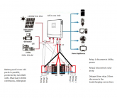
OK...... I need more info. Could you provide some kind of drawing that describes what you are trying to do?
 
OK, it is getting clearer... but I still have some questions on what is going on.
1) what All-in-one (AIO)are you using?
2) What BMS are you using?
3) What is controlling the relay? Are thes outputs from your BMS?
4) Under what conditions would relay 1 connect or disconnect the AIO to/from the grid/generator?
5) Under what conditions would relay 3 connect or disconnect the batteries to/from the AIO
6) Why do you need the relay to disconnect the solar panels?
 
@FilterGuy Hi FilterGuy
1/ A 48v 5kVA Easy Solar (for example) can handle 70A charge current from utility plus 100A from solar charge controller
2/ Chargery unit
3/ The BMS disconnect relay out put to a delay timing board(which has three relays built in)
4/ Relays 1&2 would immediately disconnect on any of the BMS profile parameters being breached And Relay 3 would follow thereafter. Thus all sources of power input would be disconected, before the battery/inverter/load elements were disconnected, thus preventing an inrush current from damaging the inverter within the All in one unit.
5/ Triggered with same conditions as 4/ above.
6/ My understanding, is that if you simply disconnect the battery from the inverter, there is an inrush of current from the solar panel array, which is still producing at full tilt, so the current spike, fries the caps or such. By taking the PV and 240v power sources 'offline' first, i'm hoping that is enough to avoid the inrush current??? I'm a newbie to all this, so my thinking might well be screwed up.....so i welcome comments.
 
Last edited:
I have never heard there is a problem with 'inrush current' from the panels (Or the grid) but maybe I have been blissfully ignorant and damaging equipment. Could you (Or someone) point me to a link that describes this?
 
@FilterGuy Hi FilterGuy
1/ A 48v 5kVA Easy Solar (for example) can handle 70A charge current from utility plus 100A from solar charge controller
2/ Chargery unit
3/ The BMS disconnect relay out put to a delay timing board(which has three relays built in)
4/ Relays 1&2 would immediately disconnect on any of the BMS profile parameters being breached And Relay 3 would follow thereafter. Thus all sources of power input would be disconected, before the battery/inverter/load elements were disconnected, thus preventing an inrush current from damaging the inverter within the All in one unit.
5/ Triggered with same conditions as 4/ above.
6/ My understanding, is that if you simply disconnect the battery from the inverter, there is an inrush of current from the solar panel array, which is still producing at full tilt, so the current spike, fries the caps or such. By taking the PV and 240v power sources 'offline' first, i'm hoping that is enough to avoid the inrush current??? I'm a newbie to all this, so my thinking might well be screwed up.....so i welcome comments.
This is definitely a theoretical problem HOWEVER I have inadvertently unhooked batteries from SCC and left panels on without issues more than once. Not saying to try this at home but just my experience. I have done this with 4 brands of cheap china SCC like make sky blue. I have not tried it with my Midnite classic.
 
I could be wrong, but I am not sure all of the relays are needed.
  • I have never seen a set-up like the one described above. If there was a real problem I would think the world of solar installers and DIYrs would be talking about it.
  • In the scenario (as I understand it), the BMS is going to disconnect the battery and *then* all the relay stuff starts happening. Consequently, by the time the relays do their thing, the event has already happened and disconnecting the inputs would not help.
  • In the condition described the current from the panels is already flowing and the controller must suddenly stop when the battery disconnects, This does not sound like a very difficult task for the electronics to handle without any side effects. (If there was a large inductance involved you could get a voltage spike, but that is not the case here).
Having said that, I acknowledge that I could be ignorant of something or misunderstand the scenario so if I need to be 'educated', please do!
You might want to read this thread....

In the scenario i indicated above, the BMS would not disconnect the battery and then the rest....opposite way about, hence the use of the delayed relay board.
I'm new to all this, so i have probably pick things up very wrong. The more i read these threads, the more confused i am getting, TBH.
 
This is definitely a theoretical problem HOWEVER I have inadvertently unhooked batteries from SCC and left panels on without issues more than once. Not saying to try this at home but just my experience. I have done this with 4 brands of cheap china SCC like make sky blue. I have not tried it with my Midnite classic.
Yeah, justin laureltec suggested similar to me, in that if it was only a rare occasion that the battery was disconnected for maintainence etc, the the system would handle it....im probably panicing about nothing...lol
 
I just skimmed through the manual for the Chargery BST8 the OP is using. Nice BMS!!!

I like the relay-delay board accessory. That will do the trick for pre-charging the inverter prior to connecting the inverter to the battery. The precharge push-button or rotary switch discussed in the some other threads aren't needed. (The translated manual kept using discharge where is should say pre-charge so it took me a while to understand it)

I don't like the power needed to drive the charge relay and the discharge relay all the time the system is on.... If you can figure out how to use the charge and discharge relay outputs to tell the Inverter-charger what to do, it might be better but that is highly dependent on the inverter-charger selected. I have the start of an idea on how to use latching relays to do this with a much lower power draw, but I need to think it through before I post it. If I can figure it out, this may be the BMS I use on an upcoming project.

I may be missing something but I still don't see a need for a relay between the solar panels and the inverter/charger or between the AC-in and the inverter-charger.
 

diy solar

diy solar
Back
Top