diy solar

diy solar

the easy way to keep your cells balanced is...active balancing

I’m not surprised by the manufacturers response. I haven’t seen a capacitor that requires a limited charge current.

The only reason i use a precharge is to protect the contactor or charge source (battery) - i’ve never personally seen a capacitor damaged by high current.

I’m curious exactly what component of the active balancer is being damaged by high current?
when dealing with a 1 farad cap for an audio system they did it to keep the batteries, fuses and breakers intact. for smaller items like what I am dealing with now, I can see it for a multitude of reasons... not the least to keep you from scorching the contact area and causing resistance. think about it, if you get a big honking spark across the area where your ring terminal contacts the buss bar, or the battery terminal itself, it would create resistance. in the case of the above poster, he claimed to have burst a cap when he plugged it in. I could see that in smaller caps getting charged from a battery that can put out 300 x its C1 for a couple of seconds. the in-rush could be fatal for smaller caps. back the day Amp makers required their trained people to do the same...but that was 12 volt and not 48. I just needed a quick and easy way to calculate the size for my system, and thanks to DIYsolar123 I have an idea from which to start.

it is possibly unneeded but how much is a 5 ohm by 500 watt resistor? pennies on the dollar and safer.. hell I can buy three different sizes going down from there and still not spend a dollar... cheap insurance.
 
it is possibly unneeded but how much is a 5 ohm by 500 watt resistor?
I don't know if that is a typo, but a 500 watt resistor is way bigger than is easily available. You can get them, but they are very costly.

I think people over-do how small a resistor they use. The idea is to charge the capacitors in the front-end of the inverter, and that won't really take too long or too much current. Recall that the capacitors will appear as a direct short for a split second. For that split second, the watts through the pre-charge resistor would be (V * V)/R = (48 * 48)/R. If you use a more nominal 40 ohm that would be 57W. That wattage would be for only a few milliseconds, as the current will go down quickly as the capacitors charge. So in that case I think you could get by with a 50W resistor. Much cheaper.
 
Higher ohms/lower watts is just as effective and even cheaper. A 500Ω, 10W resistor does the trick too (48V system).
 
I must have transposed a decimal place while I was figuring that up last night. now I am not even sure how I came up with that number.... thats what happens when you try to do math with the help of a friend helping you like Jim....Beam.. :)
 
I must have transposed a decimal place while I was figuring that up last night. now I am not even sure how I came up with that number.... thats what happens when you try to do math with the help of a friend helping you like Jim....Beam.. :)
Don't be hard on yourself - Your math was actually correct: 48 * 48 / 5 = 460 watts. So if you actually do use a 5 ohm resistor, it will be carrying 460 watts for a tiny fraction of a second. You just don't need to use a resistor that small.

So Jim Beam did you good! (But use a bigger resistor :LOL:)
 
so far no answers on what value of a resistor one should use to pre-charge these units?
I use these to precharge the caps in my 24 volt 2000 watt inverter. Precharge for 10 seconds and quickly hook up the positive cable. Zero spark.
 
I use these to precharge the caps in my 24 volt 2000 watt inverter. Precharge for 10 seconds and quickly hook up the positive cable. Zero spark.

Those are definitely under-rated, but as has been mentioned, the current drops off so quickly, it's probably not a risk.
 
Those are definitely under-rated, but as has been mentioned, the current drops off so quickly, it's probably not a risk.
If they were underated for this application wouldn't I still see a spark :) The resistors were suggested here and that's why I bought them. A 25 watt resistor might be better but I have used the same 5 watt 50 ohm resistor a few times with no problems.
 
If they were underated for this application wouldn't I still see a spark :) The resistors were suggested here and that's why I bought them. A 25 watt resistor might be better but I have used the same 5 watt 50 ohm resistor a few times with no problems.
No, it wouldn't cause a spark. The underrating that @snoobler is talking about is that there is more than 5W going through the resistor, if only for a fraction of a second. For your 24V system, the resistor is getting a bit under 12W. If you did that continuously, the resistor would probably pop on you. However, for the short amount of time the pre-charge takes, it won't hurt anything.
 
I will get a 25 watt, 30 ohm resistor to pre-charge a capacitor for the bigger inverter I will get for my 24 volt upgrade.


I did notice Will said they were a dollar, but of course I can’t find those on Amazon for that cheap, but these are not typically available at the local walmart.

Think it wa earlie run this thread that someone said the LED light resistor, The 50 watt 6 ohm resistors, won’t work. Shame those LED resistors don’t work since Those are available at most Auto Parts stores.
 
well to get this thread back on track, I ordered and received two of the heltec 15-17 active balancers (capacitor types), and started making a wiring loom for them that will allow me to place the unit away form the battery a reasonable distance.

my battery pack is about 2' x 3.5' (approximately) and the short leads i soldered onto my BMS are already pissing me off. that and the short main cables on the bms.... but I digress.

Everything I have read on the heltecs says that once you hook them up, you cannot unhook them without frying them... why is this? and which harness should i plug in first? The ones I ordered have two plugs. one has B- and B+ 1-8 and the other plug has B+9-17. I quizzed the helltec support site about what to do with the extra lead (B+17) my pack is 2p16s and they said just do not hook it up???? WTF? (honestly their website is worthless but if the unit works....)

I saw other makers of active balancing units where you had to hook up the extras in a particular fashion to keep from blowing the units... so OK... why not the same for this? different architecture?? and why can I not unhook it after hooking it up? (without damage.)

If i were to try to unhook it after words.. which lead should I pull first? I was thinking just cut the negative line as after you take it out the rest of the board would not have a ground so it should not be able to fry anything without a complete circuit. (now you chuckle heads can make fun of my lack of knowledge.)

My 2p16s pack had while undergoing charge with no draw, a maximum divergence of 0.105 volts and that disappeared within 5 minutes of putting a load on the pack. (the bms went into protect and stopped charging. in actuality after watching an almost full charge cycle with it appears I have a runner number 4/5 and a slower to charge cells 11/12 and thats where the real issue was. 4/5 ramped up to 3.51 while 11/12 was at 3.405 and that tripped the alarm for the cell differential? (sorry some of these terms are new to me). BMS was set to max of 3.65 per cell, 58.4 for the pack, with a differential of .100 volts for alarm.

my settings are 54.4 max charge from the SC. I also found out it was drifting higher actually up to 55.36 which I double checked against the BMS and my multimeter, and reset the SC to accommodate the difference between what I was requesting and what I was getting.

as quickly as the cells leveled out with a draw on them i would almost bet that there would not have been any real difference if I had been running the inverter on them to start with. It only appears at the high end while charging (to date).

Currently with two days of overcast skies and running the A/C the entire first 12 hours to dry the cabin out I am at 49% and the high and low voltage difference is only 0.004 volts difference between highest cell and lowest, so I don't think I really need this per se, but I want to see if I can fill the battery a little fuller prior to the BMS shutting down the ports. I am trying to stay in the range of 3.0 and 3.4 volts to avoid the knee's of the curve but I do want to exploit the range as best I can. if I can get in another kilowatt of storage with one of these balancers I am willing to spend the money...hell i already did. and if these batteries pan out then I will probably order another 32 of them and double my capacity. I have the panels for it so why not?
 
i got nothing out ofg 4 pages except we now need 2 bms to do the work of one, i thought 1 bms should do everything, if it is a bms, how come the one op posted doesnt balance cells, or do they all work this way
 
well to get this thread back on track, I ordered and received two of the heltec 15-17 active balancers (capacitor types), and started making a wiring loom for them that will allow me to place the unit away form the battery a reasonable distance.

my battery pack is about 2' x 3.5' (approximately) and the short leads i soldered onto my BMS are already pissing me off. that and the short main cables on the bms.... but I digress.

Everything I have read on the heltecs says that once you hook them up, you cannot unhook them without frying them... why is this? and which harness should i plug in first? The ones I ordered have two plugs. one has B- and B+ 1-8 and the other plug has B+9-17. I quizzed the helltec support site about what to do with the extra lead (B+17) my pack is 2p16s and they said just do not hook it up???? WTF? (honestly their website is worthless but if the unit works....)
I plug and unplug mine without a care in the world...no damage at all, and they are just the cheap $30-$40 ones.

for my BMS cables I always make them as a "Y" cable so the BMS always stays attached and I can swap in a balancer or a isdt batgo to look at things directly (the isdt units have a secret calibration menu so you can really adjust them to match your best multimeter) . My cells always sit within a few mv's of each other at 3.400v.
so are you using 2 x bms
 
so are you using 2 x bms
actually yes and no. one is a BMS that offers very limited balancing capabilities. the other technically is not a BMS as it does not do anything except to balance. but it has the capabilities to balance out rather large discrepancies... these are not the fualt of the BMS, but the fact that even though every seller claims tht the batteries are grade A and matched.... at the price points we are buying these cells they are not grade A and Matched... at least not fully matched. I would guess they are grade A- and only loosely sorted but not fully matched. as a result with the size of these cells you need a ability to move more energy than what the actual BMS can move if you want to get as much out of the cells as possible.

I honestly do not needs this, but its cheap under 50 bucks and its a learning experience...+ my batteries cost me around 5K USD with shipping.... whats 50 bucks to add a second layer of protection to the pack? penny wise and pound foolish is a term that comes to mind.

in the end, this is just a lark. I could pay about 10K initially and get put back on the grid... what my down the road costs would be as more folks leave the area are not something I can guestimate with the service provider in my area.
 
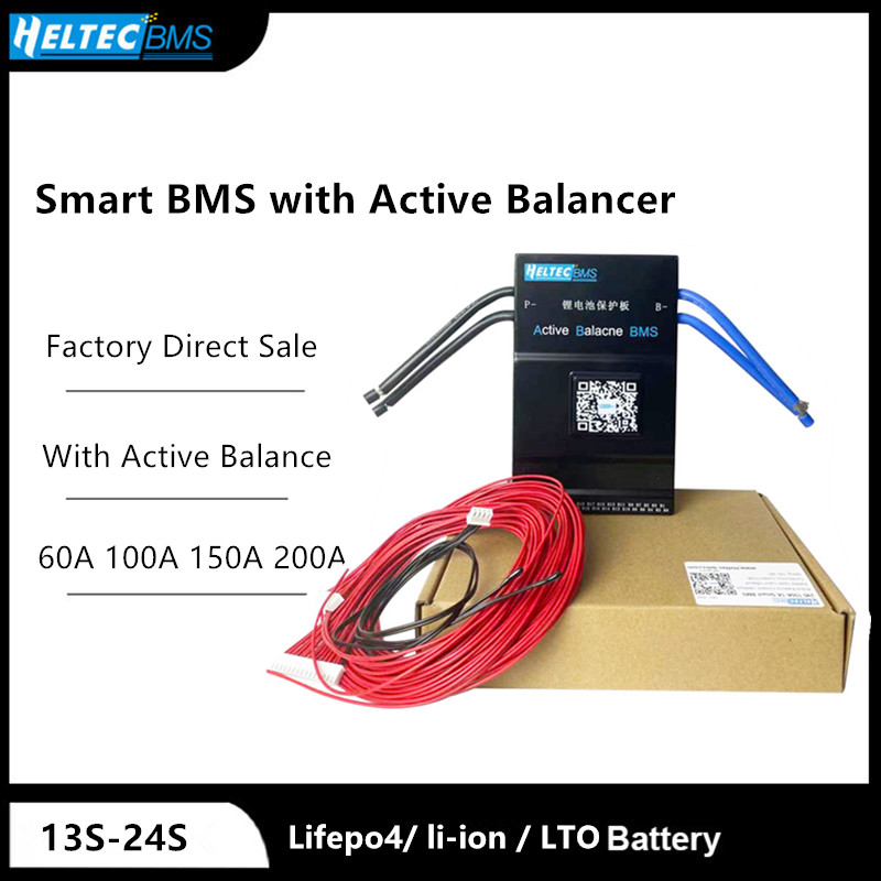
Anyone have experience with the HelTec SmartBMS? BMS with built-in active balancing and supports CANbus/RS485 communication. Seems like it would be good. I'm thinking of cancelling my order for Overkill 48V BMS and get these instead.

The website is hilariously terrible. But if the product is good and price is reasonable, who cares?


Category: SMART BMS SKU: 1026
Tags: 13-24S 200A Bluetooth Smart BMS with Active balance
Li-ion Lipo Lifepo4 LTO Smart BMS Lifepo4/LTO/Li-ion/Lipo
Support CAN / RS485 interface (optional) BMS


Edit: Oops I should have searched first. There's a dedicated thread for these:
https://diysolarforum.com/threads/heltec-jk-200a-smart-bms-with-2a-active-balance.17831/unread
They work great, but for large cells, use the 2amp balance version. My system stays around .008mv deviation most of the time.
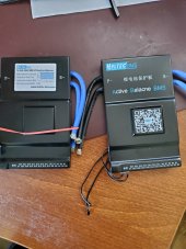
The packaging changed a bit from last year. Old on left, new on right.
 

Attachments

  • 20210802_115241.jpg
    20210802_115241.jpg
    169.2 KB · Views: 25
They work great, but for large cells, use the 2amp balance version. My system stays around .008mv deviation most of the time.
The packaging changed a bit from last year. Old on left, new on right.

Thanks, I just received my order a couple days ago. Same comical misspelling of "Balance" and documentation is weak, but otherwise the build quality seems solid. I need to get some cables and accessories this week, but hopefully will get my batteries assembled and ready for some testing soon.
 
They work great, but for large cells, use the 2amp balance version. My system stays around .008mv deviation most of the time.
The packaging changed a bit from last year. Old on left, new on right.

Did you keep the cell monitoring cables the same length for each cell, or trim them to length from BMS?

I was planning to trim mine to length from BMS, so that the nearest cell would have a shorter cable and the farthest cell would have a longer cable. That would keep my wiring loom nice and neat. But then I was reading the Victron wiring guide about how cable length impacts voltage drop & current delivery, and now I'm thinking maybe I should keep all leads the same length, and just try to coil any excess out of the way.

Or perhaps it wouldn't make any difference on these short wire lengths? Maximum difference is about 24 inches. I'm trying not to overthink every little detail, but I don't want to miss anything important either. If the BMS is relying on these readings then I suppose I should ensure they are as accurate as possible, and so now I'm leaning toward keeping 28" wires for even the shortest, 4" runs.
 
Last edited:
Did you keep the cell monitoring cables the same length for each cell, or trim them to length from BMS?

I was planning to trim mine to length from BMS, so that the nearest cell would have a shorter cable and the farthest cell would have a longer cable. That would keep my wiring loom nice and neat. But then I was reading the Victron wiring guide about how cable length impacts voltage drop & current delivery, and now I'm thinking maybe I should keep all leads the same length, and just try to coil any excess out of the way.

Or perhaps it wouldn't make any difference on these short wire lengths? Maximum difference is about 24 inches. I'm trying not to overthink every little detail, but I don't want to miss anything important either. If the BMS is relying on these readings then I suppose I should ensure they are as accurate as possible, and so now I'm leaning toward keeping 28" wires for even the shortest, 4" runs.
The resistance of say AWG 24 stranded wire is about 26 ohms per thousand feet. So the resistance difference between a 28" run and a 4" run (2 ft) is 2 x 26/1000 = 0.052 ohms. If you have 2A running through that wire, the voltage drop difference is 2 x 0.052 = ~0.1V. That's enough to make a difference if you are trying to keep your cells balanced to within something like 0.005V. So yeah, it's good to keep the balance leads close to the same length.

Note that this only matters if you have an active balancer (or a BMS with active balancing). On the more run-of-the-mill BMS the passive balancing is small enough in current that the voltage drop is pretty insignificant.
Agree. All my balance cables are the same length. The connection is just as important. A just bought some silver paste to improve the connection to lower the wire ohms on the BMS.
 
Lesson Learned DEPT:
I have Active Balancing on ALL of my packs and future packs will also, now a default add, regardless of Matched & Batched or Bulk Commodity cells. DO keep the wire lengths identical, or you WILL be chasing Gremlins... Never offer Gremlin's a Foothold or they will make life "interesting" and generally in an unpleasant manner.
 
I run 24V, all of my battery packs have a QNBBM-8S Active Balancer on them and they work quite well to keep everything nicely balanced.
Passive Balancing is essentially useless on large capacity LFP as it only burns off hi voltage cells at low power by dissipation. There have been some recent imrovement's on Active Balancers by Known Good vendors like Heltec & QNBBM (deligreen :-( ).

A NOTE: Be certain that the Active Balancer you select has enough capacity to handle the Size of your cells ! As Active Balancers transfer power between cells, the larger capacity cell balancing has to work more.

I have done extensive cycle tests & thrash testing of my packs with the QNBBMs and they take it all quite well. Thrash Tests included full C-Rate charge & discharge runs as well as other stress tests.

Charge Setting Note: (I use a Midnite Solar Classic SCC)
Absorb: 28.2 for 15 minutes
Equalize: OFF
Float 27.9V
MIn Volts: 22.0 Max Volts: 28.7
Rebulk Voltage: 27.7
End Amps: 14A
This get's the bank charged to full with high amps (Constant Current) and then float (Constant Voltage) tops off so the cells are on average between 3.475-3.500. I am running 7/24/365 so float is used up by the Inverter + provides whatever the packs will take to top off.

* Active Balancing + Float:
I've found that once the battery packs are "full" and in float mode, they barely take any input but as the Active balancers are working and levelling, the float allows for everything to fully top off evenly, all cells within all packs are between 6-10mv once float has been running for an hour. This is what I have observed with my packs.

Hope it helps, Good Luck
Hello! May I please ask which size of active Heltec balancer I would need for a 4S 420ah LiFePO4 battery pack? Thanks so much for your help : )
 
Hello! May I please ask which size of active Heltec balancer I would need for a 4S 420ah LiFePO4 battery pack? Thanks so much for your help : )
5A Active Balancer can handle up to 300AH Cells
This is the simpler 3s/4s Active Capacitance Model.
 
I use a Heltec Capacitor Active Balancer from amazon or aliexpress. Be careful when you use a capacitor active balancer , make sure you pre-charge the capacitors before you hook it up to your battery, I use a resistor on the negative lead to pre-charge the capacitors before I connect up the negative lead to the battery. With my first balancer I forgot to do that and I burned up one of the capacitor.

Can you share details of how you pre-charge the capacitors. Did you use a power supply and what value resistor? How did you set up the wiring?.
 
Last edited:
Can you share details of how you pre-charge the capacitors. Did you use a power supply and what value resistor? How did you set up the wiring?.
Please search for the precharge video by Will. Fairly self explainitory
 

diy solar

diy solar
Back
Top