Brett V
Mad Scientist
Super nice work! I need to quit being so lazy and start documenting my build with some decent photos.
For yourself, if not for all of us!Super nice work! I need to quit being so lazy and start documenting my build with some decent photos.

Great documentation. one of the things I am not that great about. . I was really digging your posts up until this point..... but those feet.... are your toes prehensile? are the digits opposable? Are you the next evolution in mankind? Damn Bro... Inquiring minds want to know!
Yeah, you should see me swinging in trees using only my feet! Funny thing is, I almost edited my feet out of the shorts where they snuck in. I also didn't post the picks that had way more of my ugly feet!Great documentation. one of the things I am not that great about. . I was really digging your posts up until this point..... but those feet.... are your toes prehensile? are the digits opposable? Are you the next evolution in mankind? Damn Bro... Inquiring minds want to know!
Bro, seriously though, good job. looks like mine minus the wood. My box is simply the insulating foam only and with the local temp drops I will soon be able to figure out how well the heating pads and temp controllers actually work. sorry folks too busy converting ethanol to methane to take photos of anything.Great documentation. one of the things I am not that great about. . I was really digging your posts up until this point..... but those feet.... are your toes prehensile? are the digits opposable? Are you the next evolution in mankind? Damn Bro... Inquiring minds want to know!
the controllers you used??? got a link? (if i missed it i was drunk and thats my story).Yeah, you should see me swinging in trees using only my feet! Funny thing is, I almost edited my feet out of the shorts where they snuck in. I also didn't post the picks that had way more of my ugly feet!
Not sure which controllers you are talking about. The thermostats? Or do you mean the solar charge controllers I installed in 2017?the controllers you used??? got a link? (if i missed it i was drunk and thats my story).
I think I saw your heating pads (although I can't find the post now), and they look pretty similar to mine. I've done a couple of tests of them on the aluminum plate and it doesn't get too hot too fast. I'm hoping 2 of the 12W pads is enough.Bro, seriously though, good job. looks like mine minus the wood. My box is simply the insulating foam only and with the local temp drops I will soon be able to figure out how well the heating pads and temp controllers actually work. sorry folks too busy converting ethanol to methane to take photos of anything.
I don't think I have any particular talent for this. In my case, the partners in owning the cabin (my brother and my sister) spend more time at the cabin than I do, but don't know what all the equipment is for or what to do with it. In addition, we are all over 60 now so the next generation will at some point have to assume responsibility for everything in the cabin, including the solar. So when I did the design of the solar in 2016 and installed it in 2017, I ended up writing a 46 page design document that walks through all the load analysis, NREL data, solar panel temperature coefficients, and everything else that drove us to the particular design that was installed, as well as how to do the settings on the SCC and Inverter.Your photos and documentation style inspired me to try... It's just not one one my talents.
yep the thermostats.Not sure which controllers you are talking about. The thermostats? Or do you mean the solar charge controllers I installed in 2017?
mine will get their first real test in the next couple of weeks. the real question is will the temp controllers I am using cycle in a way that prevents overheating? I use two of the cheap controllers in series, one actually measures and cycles the pads, the second set is a high temp cutout in case the first one does not work properly. trying to avoid the old battery catching on fire routine that seems to be making the rounds by us third tier DIYers. We read all the stuff on forums like this and think we know what we are doing... (me included)I think I saw your heating pads (although I can't find the post now), and they look pretty similar to mine. I've done a couple of tests of them on the aluminum plate and it doesn't get too hot too fast. I'm hoping 2 of the 12W pads is enough.
The ones I ended up using were two of these:yep the thermostats.
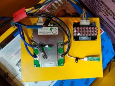
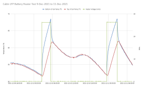
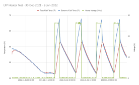
Your two thermostats in series is almost exactly what my system is set up to do. One thermostat sensor is on the aluminum plate the pads are attached to. The other one is measuring the temp on the top of the cells. You are right that if one thermostat fails, the other should prevent the batteries from getting too hot - Or at least that is the hope!mine will get their first real test in the next couple of weeks. the real question is will the temp controllers I am using cycle in a way that prevents overheating? I use two of the cheap controllers in series, one actually measures and cycles the pads, the second set is a high temp cutout in case the first one does not work properly. trying to avoid the old battery catching on fire routine that seems to be making the rounds by us third tier DIYers. We read all the stuff on forums like this and think we know what we are doing... (me included)
the ones I am using are enclosed in a plastic box. a little prettier for the not quite so gifted like myself,Your two thermostats in series is almost exactly what my system is set up to do. One thermostat sensor is on the aluminum plate the pads are attached to. The other one is measuring the temp on the top of the cells. You are right that if one thermostat fails, the other should prevent the batteries from getting too hot - Or at least that is the hope!
Yeah, when I started seeing people post that their LFP cells caught fire I almost set down my tools and stepped back from this project. The fact that my heater system could fail and wreck the cells is bad enough, but catching fire is much worse. Our cabin has no one ever in it from about mid-November until generally early May. If something isn't right the place could burn down and we would never know. We have no Internet up there, else I would put in some additional smarts to log everything and maybe send an alert if stuff is out of normal range. But all of that plus a full time Internet connection would cost more than the new cells.My internal danger meter is pinging as this is my first set of lithium's. the AGM's I had before I had plenty of experience with. never had to worry about temps as inside the battery shed it never got below freezing even when it was -15c outside.
my cabin is in range of cell towers (thank you Mt. Fuji for being a tourist magnet) and I have been asking questions about how to use a "wireless" router in reverse... IE use a wifi hotspot into the router and then a ethernet cable coming out to my inverter and SCC's and BMS. neither my inverter nor my SCC's support wireless. just ethernet, and a couple of other patch cables. so i am trying to figure out what to buy router wise so that I can use a prepaid wireless hotspot and then feed the signal into the gear with ethernet. that would make me feel much more comfortable if I could monitor via the internet. and both items can be shut down via the internet so I could set warning alerts and if XX parameter is being reached I could shut down the system until I get back. much better than fire i think. or maybe I am just too paranoid....Yeah, when I started seeing people post that their LFP cells caught fire I almost set down my tools and stepped back from this project. The fact that my heater system could fail and wreck the cells is bad enough, but catching fire is much worse. Our cabin has no one ever in it from about mid-November until generally early May. If something isn't right the place could burn down and we would never know. We have no Internet up there, else I would put in some additional smarts to log everything and maybe send an alert if stuff is out of normal range. But all of that plus a full time Internet connection would cost more than the new cells.
Mt Fuji?! You are in Japan? There must be an interesting story there.my cabin is in range of cell towers (thank you Mt. Fuji for being a tourist magnet) and I have been asking questions about how to use a "wireless" router in reverse... IE use a wifi hotspot into the router and then a ethernet cable coming out to my inverter and SCC's and BMS. neither my inverter nor my SCC's support wireless. just ethernet, and a couple of other patch cables. so i am trying to figure out what to buy router wise so that I can use a prepaid wireless hotspot and then feed the signal into the gear with ethernet. that would make me feel much more comfortable if I could monitor via the internet. and both items can be shut down via the internet so I could set warning alerts and if XX parameter is being reached I could shut down the system until I get back. much better than fire i think. or maybe I am just too paranoid....
got any more info on that Bro?Mt Fuji?! You are in Japan? There must be an interesting story there.
Years ago I took and old Linksys router and flashed it with a freeware firmware image (Tomato, I think) which allowed it to do kinda what you are wanting. You could plug wired ethernet into the four ports on the back of the Linksys, and the Linksys would connect with your WiFi, so that wired devices that were not close to your regular router could get on the Internet. I think that is called a wireless bridge. You might want to look into it. I just checked and my just retired Netgear Nighthawk R8000 can be put in wireless bridge mode, so it may be you have an old router laying around that can do it.
Not really. Have you tried to Google "wireless bridge"? That explains it pretty well, and I am more certain now that it would give you what you want. If you can find a wi-fi router that supports wireless bridge, you could have it connect to your pre-paid hot spot via wi-fi, then plug your SCC's and Inverter into the back of the router. Then you would have them all on the Internet.got any more info on that Bro?
I actually did but I am a menonite when it comes to all most anything other than specific programs on computers. years ago (pre/early pentium) I used to build my own PC's gave up even that minor task soon after the pentium 133 chips came out. too many options that I did not have time to track down and research so now I am pretty much computer illiterate unless it is handed to me on a platter. should have seen me trying to get the bluetooth dongle to work on my bms with my phone.... not a pretty siteNot really. Have you tried to Google "wireless bridge"? That explains it pretty well, and I am more certain now that it would give you what you want. If you can find a wi-fi router that supports wireless bridge, you could have it connect to your pre-paid hot spot via wi-fi, then plug your SCC's and Inverter into the back of the router. Then you would have them all on the Internet.
Looks like this one supports it: https://www.amazon.com/NETGEAR-AC1200-Wireless-Access-WAC104-100NAS/dp/B01LFSDZCU
It's got 3 ethernet ports you can use.
I'm sure there are others that can switch from router mode to wireless bridge mode. Like I said, my Netgear Nighthawk R8000 supports it. Maybe Netgear supports it on most of their routers.


