


You are using an out of date browser. It may not display this or other websites correctly.
You should upgrade or use an alternative browser.
You should upgrade or use an alternative browser.
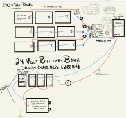
Review my diagram?
- Thread starter amberpp1
- Start date
chrisski
Solar Boondocker
- Joined
- Aug 14, 2020
- Messages
- 5,270
Don’t see fuses on the three string of panels. Two does nto reroute fuses or breakers. Three or more does.
200 ah of batteries does not seem a lot for a 3000 watt inverter. That is based off your power consumption.
I‘m not sure a SCC set to 24 volts will output 12 volts on the load Terminals. That will be in the owners manual.
For Battery monitor, that’s your choice. The SCC display only shows amperage to the system. This can be taken up by loads. For a monitor, it will give you an accurate state of charge and whether your loads are pulling more than the SCC provides and using battery power negative, or more than the loads and the battery is charging positive amps.
Noted, should I add in 15 amp fuse breakers on the positive wires coming from each string of panels before going into the mc4 connectors?Don’t see fuses on the three string of panels. Two does nto reroute fuses or breakers. Three or more does.
200 ah of batteries does not seem a lot for a 3000 watt inverter. That is based off your power consumption.
I‘m not sure a SCC set to 24 volts will output 12 volts on the load Terminals. That will be in the owners manual.
For Battery monitor, that’s your choice. The SCC display only shows amperage to the system. This can be taken up by loads. For a monitor, it will give you an accurate state of charge and whether your loads are pulling more than the SCC provides and using battery power negative, or more than the loads and the battery is charging positive amps.
My thought in using a 3000 watt inverter was that we are hoping to add more batteries in the future. Does it seem like I would be able to add 4 more batteries in the future to increase our stored energy from 4.8Kwh to 9.6kwh?
That makes sense on the monitor, it sounds like something I'd like to incorporate. Would I use a battery monitor shunt to hook the monitor up on the negative wire between the charge controller and battery bank?
Technically yes but I would skip it for this low power set up.Noted, should I add in 15 amp fuse breakers on the positive wires coming from each string of panels before going into the mc4 connectors?
chrisski
Solar Boondocker
- Joined
- Aug 14, 2020
- Messages
- 5,270
Whatever the instructions say. The shunts I’ve used get installed on the negative side.Would I use a battery monitor shunt to hook the monitor up on the negative wire between the charge controller and battery bank?
Read up on this. Short answer is with lithium yes, and with lead acid, there’s a bit of debate. I think its not wise to add lead later.Does it seem like I would be able to add 4 more batteries in the future to increase our stored energy from 4.8Kwh to 9.6kwh?
For the fuses or breakers, 15 amp fuses rated to 150 VDC would work.
So, you don’t think three sets of panels in parallel need breakers? Like to hear why.Technically yes but I would skip it for this low power set up.
acdoctor
Solar Enthusiast
SCC output amps is 125. 113 volt x 26 amps / 24 volts =122 need 3 wag or larger depending on length
Barely over the typical 15 amp short circuit rating and only 112 volts. With a little resistance the fuse may never open.So, you don’t think three sets of panels in parallel need breakers? Like to hear why.
Four in parallel running 250+ volts would be a different story. Still technically required and recommended.
You want 1AWG, not 4AWG, between the batteries and between the battery and inverter to safely handle the amperage.
I find it unlikely the load terminals of the SCC will be 12V while hooked up to a 24V battery.
Your 12V fuse box wiring doesn't make a lot of sense. The fuse box needs both a positive and a negative wire. What kind of outlet is that connected to the SCC load? What's the point of that bus bar on the negative SCC load?
I think it would be a much better plan to have proper battery bus bars that can be used to connect the inverter, the SCC, and most likely a 24V-12V DC-DC converter for your 12V fuse box. Then you can have a proper battery fuse between the battery and positive bus bar. You can have a shunt between the battery and negative bus bar.
Which SCC are you going to use? What is its max battery current output?
Here's a wire size calculator. I think a 4 AWG wire should handle 125A, but I don't know what you will be running, how long, peaks, etc. The load terminal on the charge controller is for light loads. Does the load from the controller only output while solar is coming in? You might be better to have the 12V fuse block coming from the batteries. Either way you will need a 24V to 12V converter. If the controller is 24V then I think the load is 24V.
You want 1AWG, not 4AWG, between the batteries and between the battery and inverter to safely handle the amperage.
I find it unlikely the load terminals of the SCC will be 12V while hooked up to a 24V battery.
Your 12V fuse box wiring doesn't make a lot of sense. The fuse box needs both a positive and a negative wire. What kind of outlet is that connected to the SCC load? What's the point of that bus bar on the negative SCC load?
I think it would be a much better plan to have proper battery bus bars that can be used to connect the inverter, the SCC, and most likely a 24V-12V DC-DC converter for your 12V fuse box. Then you can have a proper battery fuse between the battery and positive bus bar. You can have a shunt between the battery and negative bus bar.
Which SCC are you going to use? What is its max battery current output?
Got it, thank you. When I use a wire size calculator should I be considering the amperage to be 1.56 times the amperage I'm expecting for safety reasons, and that's why I should use 1AWG?
I hadn't thought about that for the SCC, not producing 12V will still be fine for us.
You want 1AWG, not 4AWG, between the batteries and between the battery and inverter to safely handle the amperage.
I find it unlikely the load terminals of the SCC will be 12V while hooked up to a 24V battery.
Your 12V fuse box wiring doesn't make a lot of sense. The fuse box needs both a positive and a negative wire. What kind of outlet is that connected to the SCC load? What's the point of that bus bar on the negative SCC load?
I think it would be a much better plan to have proper battery bus bars that can be used to connect the inverter, the SCC, and most likely a 24V-12V DC-DC converter for your 12V fuse box. Then you can have a proper battery fuse between the battery and positive bus bar. You can have a shunt between the battery and negative bus bar.
Which SCC are you going to use? What is its max battery current output?
I wanted to also say that I am not sure what I was thinking with the 12Vdc load there and all that mess. We really don’t even need the 12V per say so I will scrap that.
I was going to use the Midnite Solar Classic 150MPPT, with 4 SOK batteries. The batteries are 12V 100ah, their max continuous discharge rate is 100A with a peak discharge current of 200A before shutting off after a few seconds.
Does this look more reasonable?
Attachments
3000W / 24V = 125A. Take into account some inefficiencies and call it 150A. Looking at a good wire/amperage chart such as that provided by Blue Sea Systems gives you a recommended wire size of 1AWG. Then you want to pick a proper fuse for the inverter to protect the wire. Use a max of 250A fuse on a single 1AWG wire or about 175A if it's bundled with others. Pick a fuse bigger than the loads to avoid nuisance trips. So I would pick a 175A fuse between the inverter and battery.When I use a wire size calculator should I be considering the amperage to be 1.56 times the amperage I'm expecting for safety reasons, and that's why I should use 1AWG?
A 1.56 factor is a bit much for choosing the wire. Using oversized wire will only hurt your wallet as long as the bigger wire physically fits the terminals you are dealing with.
What is the output current to the batteries for this SCC? That will determine whether your proposed 8AWG is sufficient.I was going to use the Midnite Solar Classic 150MPPT
Note that the discharge current of your batteries is irrelevant for the SCC. For the SCC you should worry about the battery's recommended charge current. For the SOK 12V 100Ah battery that is 40A. You will have two in parallel so you get 80A recommended charge current and a max charge current of 100A. So make sure your SCC will only deliver 80A on a regular basis.
The battery max continuous discharge is relevant for your inverter and other loads. Again, with two in parallel you have 200A max continuous discharge and 400A peak for 3 seconds. But with a 3000W inverter you'll never get close to 200A. And the 175A fuse will blow before that could happen anyway.
Your updated diagram leaves me with a few comments:Does this look more reasonable?
1. Why have a negative battery bus bar but not a positive? You really should have both. Then the parallel batteries can be connected properly and then things like the SCC and inverter can be connected to the bus bars. If you later add DC loads (and DC fuse boxes) then they can be connected to the bus bars too.
2. The 8AWG wire from the SCC needs to be confirmed based on it's output current as mentioned above.
3. Panels that are 3 or more in parallel (your case) normally need a combiner box with proper fuses on each string.
4. You need a fuse between the inverter and battery as I mentioned above.
5. You need a master battery fuse between the batteries and positive bus bar.
6. You might want to replace the fuse you have between the solar panels and SCC with a breaker that can act as a disconnect switch.
7. Same with the fuse between the SCC and batteries.
Hopefully others give some feedback as well.
I have reconfigured my diagram and included an array combiner. After further research I think it would be better for me to go with the Victron 150V/45A SCC if that is suitable for this array like I think it is.
I have 4 SOK batteries but they are the 12V 100Ah, rather than the 12V 206Ah. I think this means my batteries max charge current will be 100A, and their preferred charge current 40A when wired in 2S2P.
I felt like I was getting a handle on sizing the wires, fuses/breakers, but now I am again unsure. My thought process was to provide...
1. Each string of panels with a 150V 15A breaker as each string will produce an open circuit voltage of 112.8V and a short circuit current of 8.85A.
2. A 50A breaker between the SCC and batteries as the SCC will be giving a max of current of 45A to the batteries that ask for 40A.
3. A 100A fuse between the inverter and batteries as the 2000W/24V Giandel inverter could try to pull about 83A.
This leaves me with the question of sizing the master battery breaker. Would this breaker be 200A or more as that's what the current in the batteries will be?
My ill-confidence comes from trying to use a few wire calculators and a blue seas wire sizing chart which I found to be giving me very different answers.
Thank you to those of you who have given me some feedback, I appreciate any advice on the wire and breaker sizing
Attachments
chrisski
Solar Boondocker
- Joined
- Aug 14, 2020
- Messages
- 5,270
A couple of comments:
1) The SCC may not produce as many amps as the panels are capable of. If you plan this, than fine. Math in my head says for every 200 watts of panels you can charge a 24 VDC system at 6 amps. Math in my head puts this around 65 amps.
I don’t get 100% with my flat mounted RV panels, I get about 60%. For my portable panels, that I tilt and place in the shade, I get close to 100%.
2) Wire ampacity: The wires I looked at from the combiner to the SCC and the SCC to the batteries don’t seem like they may handle the load. You have 10 AWG whinch can handle 30 amps and 14 AWG that can handle 20 amps. I like to do my builds planning for 60C insulation since the higher C ones could but if the wire gets that hot.

3) for the inverter, seems like you planned your build as if you’ll always get 24 VDC, but there is a low voltage cutoff of around 20 VDC And also 15% efficiently losses. A 2000 watt load will pull 2300 watts from the battery. When charging at 28 VDC, the 2300 watts pills 82 amps, but at low VOltage cutoff, this turns to 115 amps. There should be some play in that.
This means the fuse should be perhaps 125 amps, maybe 150. In the resources section of this website once you’ve determined the amperage, there’s a download for figuring fuses. The inverter manual probably says to use a class T fuse, which is pricey.
4) Battery fusing: You don’t need to fuse at max battery output, that is the highest you expect to see. For 200 amps its to protect the wiring. If you put a 200 amp fuse, you’d Need to make sure the wiring matched it. In the chart above, that says 3/0.
If you don’t expect high DC loads, you could probably fuse the battery for the same as the inverter. That would be your inverter is your one high amperageload and nothing else compares..
1) The SCC may not produce as many amps as the panels are capable of. If you plan this, than fine. Math in my head says for every 200 watts of panels you can charge a 24 VDC system at 6 amps. Math in my head puts this around 65 amps.
I don’t get 100% with my flat mounted RV panels, I get about 60%. For my portable panels, that I tilt and place in the shade, I get close to 100%.
2) Wire ampacity: The wires I looked at from the combiner to the SCC and the SCC to the batteries don’t seem like they may handle the load. You have 10 AWG whinch can handle 30 amps and 14 AWG that can handle 20 amps. I like to do my builds planning for 60C insulation since the higher C ones could but if the wire gets that hot.
3) for the inverter, seems like you planned your build as if you’ll always get 24 VDC, but there is a low voltage cutoff of around 20 VDC And also 15% efficiently losses. A 2000 watt load will pull 2300 watts from the battery. When charging at 28 VDC, the 2300 watts pills 82 amps, but at low VOltage cutoff, this turns to 115 amps. There should be some play in that.
This means the fuse should be perhaps 125 amps, maybe 150. In the resources section of this website once you’ve determined the amperage, there’s a download for figuring fuses. The inverter manual probably says to use a class T fuse, which is pricey.
4) Battery fusing: You don’t need to fuse at max battery output, that is the highest you expect to see. For 200 amps its to protect the wiring. If you put a 200 amp fuse, you’d Need to make sure the wiring matched it. In the chart above, that says 3/0.
If you don’t expect high DC loads, you could probably fuse the battery for the same as the inverter. That would be your inverter is your one high amperageload and nothing else compares..
60A would be better assuming the wire is safe with that. 50 is too close to 45 and you run the risk of nuisance trips.2. A 50A breaker between the SCC and batteries as the SCC will be giving a max of current of 45A to the batteries that ask for 40A.
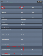
A single SOK battery supports 100A max continuous discharge and wants a 40A charge. With two in parallel you can double both of those. So your 2S2P battery setup is fine with 200A continuous discharge and 80A charge, all at 24V.I have 4 SOK batteries but they are the 12V 100Ah, rather than the 12V 206Ah. I think this means my batteries max charge current will be 100A, and their preferred charge current 40A when wired in 2S2P.
Just to triple check, this was the chart I was referencing which is under the specifications for the SOK batteries found through one of Will's links. Am I looking at the wrong chart? I just really want to be sure of what they should be charging at60A would be better assuming the wire is safe with that. 50 is too close to 45 and you run the risk of nuisance trips.
A single SOK battery supports 100A max continuous discharge and wants a 40A charge. With two in parallel you can double both of those. So your 2S2P battery setup is fine with 200A continuous discharge and 80A charge, all at 24V.
Attachments
The actual SOK spec sheets were posted here:

 diysolarforum.com
But I did get the 40A recommended charge current from the 206Ah battery. It does seem that the 100Ah wants 20A. So sorry for that mistake. I like my SOK batteries but I don't particularly trust the SOK spec sheets. There do seem to be some mistakes and contradictions. I even emailed SOK about some numbers and the reply I got contains quite a few glaring contradictions. For example, the 206Ah battery spec sheet states 40A recommended charge and 50A max charge. While the 100Ah spec sheet states 20A recommended but it also states the same 50A max. That seems wrong to me but maybe it's fine.
So anyway, it would seem with your 2S2P SOK 100Ah battery layout it would be 40A charging, not the 80A I originally posted
SOK LiFePO4 specs: 100Ah vs 206Ah
The SOK website lists basic specs for each of their batteries. But, apparently the only place you can currently download detailed spec sheets is the SOK Facebook Group. I've attached the spec sheets for their two original 12v batteries (100Ah and 206Ah). Specs sheets for their two newer...
diysolarforum.com
But I did get the 40A recommended charge current from the 206Ah battery. It does seem that the 100Ah wants 20A. So sorry for that mistake. I like my SOK batteries but I don't particularly trust the SOK spec sheets. There do seem to be some mistakes and contradictions. I even emailed SOK about some numbers and the reply I got contains quite a few glaring contradictions. For example, the 206Ah battery spec sheet states 40A recommended charge and 50A max charge. While the 100Ah spec sheet states 20A recommended but it also states the same 50A max. That seems wrong to me but maybe it's fine.
So anyway, it would seem with your 2S2P SOK 100Ah battery layout it would be 40A charging, not the 80A I originally posted
Do you think it would make more sense to use a Victron 70amp charge controller then? Would I be able to program (as a beginner) this controller to suit the SOK batteries?A couple of comments:
1) The SCC may not produce as many amps as the panels are capable of. If you plan this, than fine. Math in my head says for every 200 watts of panels you can charge a 24 VDC system at 6 amps. Math in my head puts this around 65 amps.
Setting up a Victron SCC for the SOK batteries is very easy. You can pretty much use the default values you get when you choose the LiFePO4 preset. You'll want to update the max charge current to 40A for your batteries.
chrisski
Solar Boondocker
- Joined
- Aug 14, 2020
- Messages
- 5,270
Do you think it would make more sense to use a Victron 70amp charge controller then? Would I be able to program (as a beginner) this controller to suit the SOK batteries?
Maybe. If these are flat mounted panels and your energy audit says 45 amps is good, than 45 amps is fine.
A 70 amp would get perfect output, but you need to look at a solar calculator like in my signature block to see if you will come close to this prefect output.
I bought my 100/50 SCC because the 100/30 Victron SCC would not push out the 36 amps on my 12 volt battery my 600 watts of panels were capable of in ideal conditions. Since these are flat mounted and I use the RV in the cooler times of year not when its crazy hot in Arizona, but I max out between 25 amps and 30 amps charging to the battery. So in my case a 100/30 would have worked.
For me, things like that are really hard to calculate on paper before the build, and are a little easier after. For the three small builds I've done, there's always something to tweak that the calculators won't provide. The latest was how much the tree shading cuts into my solar powered generator when cooking with the crock pot.
Yes for my Victron SCC you could.Would I be able to program (as a beginner) this controller to suit the SOK batteries?
If the battery has a spec sheet, its as easy as programming the spec sheet. For the small 25 ah lithium I built myself, I'm floating at the 24 hour no load resting voltage, 26.7, and charging slightly more at 27.5, a bit short of the max 3.65 per cell or 29.2 votls.
Similar threads
- Replies
- 23
- Views
- 943
- Replies
- 4
- Views
- 270
- Replies
- 2
- Views
- 189
- Replies
- 5
- Views
- 852