You are using an out of date browser. It may not display this or other websites correctly.
You should upgrade or use an alternative browser.
You should upgrade or use an alternative browser.
Ryobi Zero-Turn Mower SLA to LiFePo4 Conversion - (Updated - Build Complete With Pics!)
- Thread starter AMDPower
- Start date
AMDPower
New Member
- Joined
- May 18, 2021
- Messages
- 123
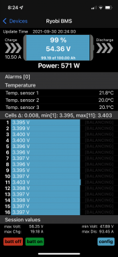
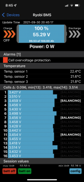
Well that was a bonehead thing of me. When I disassembled the handle, I didn't have the pins out far enough. It was barely making contact which arced and tripped the GFCI. Fixed that and the mower chargers properly! My cells are definitely more balanced. Everything looked perfect. I went to the garage and came back and the charger was off (it has a fan). Looked and it was at 100%. Here's the thing, it looks like right at the end it still got a "cell overvoltage protection" alarm. Is this normal? Or is it maybe that the cells still have a little bit of balancing left? Couple more cycles?


AMDPower
New Member
- Joined
- May 18, 2021
- Messages
- 123
Also, this charger really isn't great quality. Especially scares me because when I plug in the unit while the switch is OFF, my lights in the shed dim for a sec from surge! Might just take it apart again and make sure they have the line wired properly.
Hedges
I See Electromagnetic Fields!
- Joined
- Mar 28, 2020
- Messages
- 21,833
None of the "max" shown look over-voltage to me, 3.514V?
Was it perhaps higher when the alarm was triggered?
The goal is to get cells balanced well enough, and to charge to some voltage such that no cells are over-voltage, and BMS doesn't disconnect.
But still high enough voltage that some imbalance shows up in voltage (if not perfectly balanced) and balancing occurs.
If lights dimming was just inrush charging capacitor, not terrible but ideally would have a soft start (precharge) built in.
GFCI tripping - Did that continue? Or were you able to use the charger plugged into GFCI outlet?
EMI filter to ground is one thing which can do that. This path of line voltage making some mA of ground current is something I'm currently investigating at work.
AMDPower
New Member
- Joined
- May 18, 2021
- Messages
- 123
I get inrush but didn’t expect it while the hard power switch was OFF. Obviously they are not using that switch to disconnect mains or maybe something is wrong. It’s an integrated IEC/Fuse/switch so I would expect OFF to be Mains off. But there is inrush while the switch is OFF and I plug in the power. Gonna take a look.
AMDPower
New Member
- Joined
- May 18, 2021
- Messages
- 123
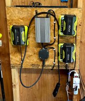
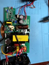
The switch just disconnects the secondary side of the supply. I've been able to solve the GFCI problem by just making sure to leave the supply powered off before connecting it to the mower and then turning on after connecting it. I think I'm going to dial down the charge voltage to 56.8V instead of 58.4V though. I'm still getting a cell overvoltage error right at the VERY end of charge which causes the disconnect before the charger drops amperage and stops. It will also be better for lifespan and I don't need the capacity. I'm pretty sure it's VR2 on the board as I believe it's next to the charging controller. @Hedges , does that look right?

Hedges
I See Electromagnetic Fields!
- Joined
- Mar 28, 2020
- Messages
- 21,833
Don't know ... I haven't spotted VR2 in your photo either.
I wouldn't have expected a voltage regulator to control the output, rather to power internal circuitry. But possible.
It would have to be an adjustable one.
First thing I'd try is the temperature sensor input, both tracing it to see where it goes and testing with a variable resistor.
Since lead-acid gets a boost voltage and a float voltage, would need a mechanism to switch between the two.
There may be a switcher control IC. It would take feedback from the output and adjust PWM of transistors to regulate.
Hedges
I See Electromagnetic Fields!
- Joined
- Mar 28, 2020
- Messages
- 21,833
VR2 variable resistor, one of three on the board.
(For some reason I was thinking variable regulator).
Sure, try that. Measure resistance in-situ first, so if turning it doesn't change output voltage you can return it to original position.
I see two ICs - look up their part numbers to get an idea how the board functions.
(For some reason I was thinking variable regulator).
Sure, try that. Measure resistance in-situ first, so if turning it doesn't change output voltage you can return it to original position.
I see two ICs - look up their part numbers to get an idea how the board functions.
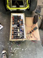
Finished my conversion today. Also looking into a better way to charge. I also bought the same charger, waiting for it to arrive. Looking to either reuse the cord and plug or attached the plug to the new charger cable.
I'm running Lishen 78ah lifepo4 from battery hookup with Daly bms. Made busbars from 1/2 copper pipe, designed and printed covers for the terminal covers that snap to the flattened 1/2 pipe.
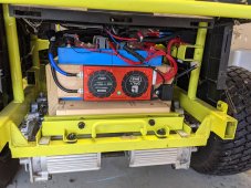
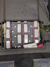
I'm running Lishen 78ah lifepo4 from battery hookup with Daly bms. Made busbars from 1/2 copper pipe, designed and printed covers for the terminal covers that snap to the flattened 1/2 pipe.


rio
New Member
Wow, that looks great! Please let us know how it works out. I'm exploring my options on how to tackle this myself. I'll keep an eye on battery hookup. How much did you pay for the cells? Right now I'm considering the easy route of trying out the cheap 12V 100Ah options on Amazon (like Ampere Time or Chins).
About $750 shipped. I haven't had a chance to give it a real test yet. Rained all weekend, but will keep you posted. My only concern is the 150 amp Daly bms. I know Daly is higher quality than most Chinese bms, but it's still Chinese bms. It came with 6awg wire and that's not going to hold up to 150amps but for a few seconds. This is my only flaw I think. I'm going to give it a good run through some high grass and see how hot the 6 awg wire gets. The wires on the factory lead acid is 4awg.Wow, that looks great! Please let us know how it works out. I'm exploring my options on how to tackle this myself. I'll keep an eye on battery hookup. How much did you pay for the cells? Right now I'm considering the easy route of trying out the cheap 12V 100Ah options on Amazon (like Ampere Time or Chins).
AMDPower
New Member
- Joined
- May 18, 2021
- Messages
- 123
Looks good! I haven't had any problem with the Overkill 100A BMS. The mower rarely peaks to 100A. I think the max I hit according to the BMS was 91A during my mow in a dew filled yard and many hills. The charger works fine but I do need to dial it down. For the GFCI trip, I definitely just have to connect it before turning it on or the arc trips the GFCI. I reused my old cable and connectors and spliced them in an electrical box. The cord that comes with the charger is complete crap. You won't want to use that one. I'm also looking into using an ESP32 with an OLED display as a battery meter. I'll let you know if I figure that one out. I got my 100AH cells through Michael for around $800 shipped. Was originally going to get 75AH but figured the 100AH would have greater current draw. What is the max draw of the cells you have?
Also, are you concerned at all about the exposed cells and no padding? I packed mine in foam and built a box because I was afraid of them getting splashed and/or taking heavy jolts on the mower. Not sure if that was overkill or not.
Also, are you concerned at all about the exposed cells and no padding? I packed mine in foam and built a box because I was afraid of them getting splashed and/or taking heavy jolts on the mower. Not sure if that was overkill or not.
Last edited:
AMDPower
New Member
- Joined
- May 18, 2021
- Messages
- 123
Hedges
I See Electromagnetic Fields!
- Joined
- Mar 28, 2020
- Messages
- 21,833
I also put a layer on top before I screw the cover on it.
Don't want concentrated force on the terminals, if batteries bounce when hitting a bump. Not as likely for a mower than some other mobile applications.
The foam should help; terminals would press into foam, and form would hold batteries with other areas. Although, busbars would probably take a lot of that and apply force through terminals.
So a hold down mechanism, perhaps foam bearing on body of cells rather than terminals, could be good for applications that jostled around more.
One member laid a sheet of plywood on top of his bank to spread his weight while reaching points further back. We think one high terminal to the brunt of his weight, causing damage and later failure.
rio
New Member
Did either of you consider these from Battery Hookup at some point? https://batteryhookup.com/products/new-battery-hookup-lifep04-32650-3-2v-5000mah-cells-1
They're cylindrical cells, and there's been some positive results reported. I can get 16 'cells' for $880. Not sure how they compare to prismatic cells in terms of durability, etc., but they're packed and stocked here in the US. Looks like I can get a very comparable price for prismatic cells from Amy Zhang, too.
Also, I was thinking of adding something like this for monitoring the battery: https://www.amazon.com/dp/B088RG27L...colid=HTUVLT52UC6V&psc=1&ref_=lv_ov_lig_dp_it. Bluetooth from the Overkill BMS is nice, but it would be nice to also have a physical gauge showing values at all times.
It's good to hear that your current peaked at 91A. Roughly how much current draw did you peg during flat straight lines? I saw that there is a 125A fuse built into the power line in the mower, which probably means the intended peak current is quite a bit below that.
AMDPower
New Member
- Joined
- May 18, 2021
- Messages
- 123
Don't want concentrated force on the terminals, if batteries bounce when hitting a bump. Not as likely for a mower than some other mobile applications.
The foam should help; terminals would press into foam, and form would hold batteries with other areas. Although, busbars would probably take a lot of that and apply force through terminals.
Are you saying it's better to have them open @tentious? I don't see what keeps them from bouncing up and down except the weight. Do you think that's OK to have them exposed like that? I do like his terminal caps though. Those are pretty neat! The foam I used on the top was the slotted foam that the batteries sat in. So they are semi-open. Mainly because I had that left over. I suppose I could just make sure they stay within the cells so they aren't on top of the terminals. Is that what you mean?
AMDPower
New Member
- Joined
- May 18, 2021
- Messages
- 123
Did either of you consider these from Battery Hookup at some point? https://batteryhookup.com/products/new-battery-hookup-lifep04-32650-3-2v-5000mah-cells-1
They're cylindrical cells, and there's been some positive results reported. I can get 16 'cells' for $880. Not sure how they compare to prismatic cells in terms of durability, etc., but they're packed and stocked here in the US. Looks like I can get a very comparable price for prismatic cells from Amy Zhang, too.
Also, I was thinking of adding something like this for monitoring the battery: https://www.amazon.com/dp/B088RG27L...colid=HTUVLT52UC6V&psc=1&ref_=lv_ov_lig_dp_it. Bluetooth from the Overkill BMS is nice, but it would be nice to also have a physical gauge showing values at all times.
It's good to hear that your current peaked at 91A. Roughly how much current draw did you peg during flat straight lines? I saw that there is a 125A fuse built into the power line in the mower, which probably means the intended peak current is quite a bit below that.
I honestly hadn't seen those cells! They look pretty neat and that's a good price. It doesn't look like they handle quite as much current but it's probably enough (1C). I noticed during straight lines something like 60A. With just the blades running and sitting still, it was around 20A. That meter looks pretty cool. Is it the same dimensions as the Ryobi by chance? Can you configure it for LiFePo? I might look into that.
rio
New Member
They're rated for 100A continuous and 200A peak (10 sec). But with the 125A fuse in the mower, I feel it's more than enough.I honestly hadn't seen those cells! They look pretty neat and that's a good price. It doesn't look like they handle quite as much current but it's probably enough (1C). I noticed during straight lines something like 60A. With just the blades running and sitting still, it was around 20A. That meter looks pretty cool. Is it the same dimensions as the Ryobi by chance? Can you configure it for LiFePo? I might look into that.
I'm not sure if the meter is the exact same dimension as the one in the Ryobi but at 2in diameter looks very close. If I can't fit it in as a direct replacement then I thought I would 3D print a mount for it on the left side somewhere. It should work with any type of battery: you just connect it in line with the load and configure it when the batteries are fully charged (and you specify the capacity). Then, it just integrates current flow over time to determine SoC. At least that what I gather from reading some of the reviews.
AMDPower
New Member
- Joined
- May 18, 2021
- Messages
- 123
They're rated for 100A continuous and 200A peak (10 sec). But with the 125A fuse in the mower, I feel it's more than enough.
I'm not sure if the meter is the exact same dimension as the one in the Ryobi but at 2in diameter looks very close. If I can't fit it in as a direct replacement then I thought I would 3D print a mount for it on the left side somewhere. It should work with any type of battery: you just connect it in line with the load and configure it when the batteries are fully charged (and you specify the capacity). Then, it just integrates current flow over time to determine SoC. At least that what I gather from reading some of the reviews.
Ahh... I see. It's an amp monitor. Similar to one I have with but yours is a much better form factor Voltage / Amp Meter. Mine is hall effect. I was thinking of 3D printing a mount for mine but if that's a drop in, I might just buy that. Will have to measure.
I thought about the bouncing as well and while the cells are not compressed, they are quite snug. I added a thin piece of foam to the bottom of the batteries to provide some cushion for movement. It would take some serious holes/bumps to toss the batteries up. My next task just to provide some additional bounce support is design and print some clips to hold the sides. I also thought of a strapping mechanism, but afraid of tension and stress on the side of the cells. I don't want foam on the cells as it will insulate the cells, potential for thermal issue.Are you saying it's better to have them open @tentious? I don't see what keeps them from bouncing up and down except the weight. Do you think that's OK to have them exposed like that? I do like his terminal caps though. Those are pretty neat! The foam I used on the top was the slotted foam that the batteries sat in. So they are semi-open. Mainly because I had that left over. I suppose I could just make sure they stay within the cells so they aren't on top of the terminals. Is that what you mean?
AMDPower
New Member
- Joined
- May 18, 2021
- Messages
- 123
Something like this might be easier/better. Voltage based only and configurable curve for battery type. Can just hook it up to 48V and power on with the key.
Maybe easier, but a shunt would more accurately keep track of SOC vs voltage. You also get current, which I would be interested in seeing.
Something like this might be easier/better. Voltage based only and configurable curve for battery type. Can just hook it up to 48V and power on with the key.
rio
New Member
That does seem more convenient. I wonder how well voltage-based SoC monitoring works with LiFePO. I'm so used to it being supper crappy with the SLAs in the Ryobi that I thought measuring actual current would be a much better way. But I suppose we can always calibrate as needed against the Overkill bluetooth data.
Something like this might be easier/better. Voltage based only and configurable curve for battery type. Can just hook it up to 48V and power on with the key.
Similar threads
- Replies
- 3
- Views
- 369
- Replies
- 16
- Views
- 399
- Replies
- 7
- Views
- 863
- Replies
- 2
- Views
- 287


