diy solar

diy solar

Ryobi Zero-Turn Mower SLA to LiFePo4 Conversion - (Updated - Build Complete With Pics!)

Anything else I should do? Thoughts? Also, thanks everybody for your help!

Can you apply a test load (rather than driving the mower)?
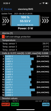
Check BMS reported cell voltages under load. Check with DMM.
Ideally, check voltage from one cell terminal to the next which is shorted to it by busbar. That way DMM reads near zero volts for more digits resolution, rather than near 3.5V, but probably not accessible.

After a heavy load (e.g. test load for a period of time, or after a vigorous mowing run, check temperature of each busbar. Any hotter than others would mean poor contact.

One other question I have... Since I don't need anywhere near the capacity. Do you think I should change the max charge to something less than 100% to maximize battery life? I know this is the case with my car which uses Lithium Ion. Is LiFePo4 similar with max charge and longevity?

Typically LiFePO4 cells are balanced once up to 3.65V and some tail current, then charged each time to a lower voltage like 3.5V.
Lower voltage for storage would be less degradation. Holding at higher voltage allow cells to diverge enough to balance.

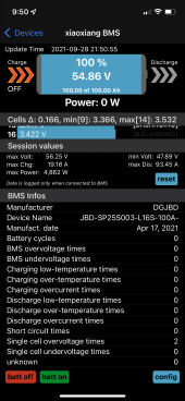
If your mowing session uses 50% +/- of capacity, I'd think that would be a good SoC for storage. Then recharge shortly before next use.


You didn't report on top balance experience. To what voltage do you charge? How far apart were the cells at that max voltage?
Goal is to have charge/discharge always stop without reaching limits where BMS disconnects (for either pack voltage or cell voltage & voltage differences)
 
This makes me sad that I didn't buy one of these now.

I love my cub cadet but man. The quiet...
 
Since you now have a lifepo4 mower you could change the charger to solar, and have it power your garage, or house daily needs, a small 100W panel could easily trickle charge it in a week I'd think. For between mowings, and if more panel is needed, it wouldn't be difficult. Plug it into a setup in a shed or garage.
 
I didn't balance it correctly. I used too low of a voltage 3.2v and charged each cell manually. But now that I watched Will Prowse's video, I realize I should have connected them in parallel, charged at higher voltage and then disconnect when amps go down (I do have a 5A bench power supply). But now that it's already rigged up... Can the BMS be used to balance while off charge? What should I be looking for in the BMS. I did get a cell overvoltage error the first time. I set the full voltage on the BMS to 3.45 and when it hit that, I had a delta of 0.17. What is "normal"?

Thanks!
If anything you'd want the bms to do that on charge as it most likely bleeds power to resistors rather than actively moving it.

But that's a question for the user manual of that bms, if there even is one.

You might not want to use that specific charger for the mower though if you can get a power supply on there for 3.5v per cell (56v) and just hold it there for a bit and see what the cells do.

It would be a pain to tear stuff back apart to balance it.

HOWEVER.

If you don't have issues with the BMS cutting off at whatever the highest voltage and full charge of your charger gives you, then chances are its close enough and you can just let the bms do the rest over time.


I'd consider a dedicated 48v lithium charger though.
 
Oh it's got a user manual! A very detailed 80 page one (https://github.com/FurTrader/OverkillSolarBMS/raw/master/Overkill_Solar_BMS_Instruction_Manual.pdf)!

Yeah, I think I'm just going to lower the full charge voltage and likely get new charger. The Overkill Solar BMS shouldn't need whatever BMS software is on that Ryobi charger. There is also thermistor that I can likely remove. that goes back to the charger.

I figure lowering the full charge to like 3.3 - 3.4 rather than 3.5 should be healthier for the battery and safer even if it is off slightly at the top. I just don't need the capacity. I got these batteries for the current rating mainly. And the lifecycle is definitely not going to be my issue. If I'm only doing 1/2 a charge cycle a week and the battery is rated for 3000 cycles...that's like...115 years?!!! I'm pretty sure something else will go wrong before then...like me an my offspring's death.
 
Just make sure if the bms has a voltage cutoff for balancing that it's set just under your charger voltage and you should be golden eventually.
 
Once your assembled pack is relatively fully charged through BMS, you can use a bench supply to top-balance by charging one cell at a time.
Set the supply to 3.65V and some current (e.g. 10A). You can observe CV while it is open circuit, then observe CC with the supply shorted. After confirming settings, connect to one cell and wait for it to charge in CC mode, switch to CV mode, then current tapers off to some target (e.g. 1A).
Do NOT turn up voltage setting while connected to the cell.
Top off each cell one at a time, and the pack is then top balanced.

But top balancing may or may not be needed. When your charger charges battery to its max voltage, at that point what are the cell voltages? If very different, needs balancing.
 
I'm running a full charge right now to check. Gonna check at a half hour and then full charge check the balance. I'll post. Thanks for all the advice!
 
OK. Here are the results. It reached full charge quicker than I thought. It's definitely not balanced but is this "way" off? Also, could I charge a single cell while in series with the pack or should it be completely physically removed?
 

Attachments

  • IMG_1949.PNG
    IMG_1949.PNG
    844.4 KB · Views: 66
3.598 max, 3.381 min, 0.217V difference.
Kind of far apart.

No need to disassemble anything. Just stop charging pack, and charge each cell to 3.65V (stopping at some tail current) one at a time.

Bad leads and cheap alligator clips will drop significant voltage. Some good solid ones would be better.
Not assembled, people make leads with ring terminals and 16 awg to 12 awg wire.
You could use good clips, jumper cables? or whatever. Make sure they aren't going to short anything.

"56.25V max"
Is that the BMS disconnect? Would be 3.516V/cell average.
How high a voltage does the charger deliver?
 
My guess is 56V. I can't charge right now because it's at max. The Ryobi charger just says 48V-13A but it's obviously not charging at 48V max. Here is the rest of the information from the BMS readout. I really think I need to dump the Ryobi charger. Everytime I get a cell overvoltage protection and reach full charge, it send the charger into a fault state and I can hear a relay click. Also, does cell overvoltage protection in the BMS app just mean that it reached full or does it mean there is a problem?
 

Attachments

  • IMG_1950.PNG
    IMG_1950.PNG
    839.8 KB · Views: 28
Image says "BMS overvoltage times 0"
Did it report cell overvoltage?

You want battery charger to stop at a voltage which doesn't cause BMS to disconnect.
Cell imbalance means some will get higher than others. You want them to stay close enough and max voltage low enough that no cell goes overvoltage, and no "imbalance" error causing disconnect.

Top balancing should help, then try to set up a battery charger which charges high enough for rebalancing to occur, but not too high.
Maybe a nice SCC and PV array. As people said, your lawn mower could power your house during power outages.
 
It reported cell overvoltage protection. You can see it at the top of the first image. Ahh... I thought the BMS just handled that. I gotta pull the specs on that charger. It looks like it is actually made by Delta-Q.
 
"Temperature compensation Yes, third pin on paddle/receptacle"

Don't want that active for lithium. Did you see a temperature sensor when you removed old batteries? See what charger does (charge voltage) when that is open-circuited.
 
Yes and I do have it connected to the positive lug. I'll try disconnecting it.
 
Ok, what is happening, is your charger is going into fault state, the BMS is actually balancing the high cells, so eventually it will bring the pack closer. The issue is, you have a LOT of low state cells… look at your chart of cells. Each one that is low needs to be individually brought up to 3.65, 0A.
The reason your charger hits over voltage is because it is expecting the lead resistance curve, and the high cells are charging up too fast.
Once the low state cells get brought up to the high state ones, the charge will be more equal across the board, and the charger likely won’t complain as much.
 
Because 3 of your cells are at high state, one is very high state, so when the charger puts pack voltage in, one cell hits BMS disconnect, and drops out the pack, and the voltage from the charger spikes to max, causing an error.

Get em all up to 3.65. Or at least all the 3.3 and 3.4v cells. Once all are near same level, the charger will stop having issues.
 
Back
Top