diy solar

diy solar

48v 64 cell SAB 60280 Batrium K9 Rack Build

Gr00ldude48

New Member
Joined
Jul 6, 2021
Messages
127
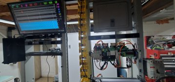
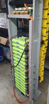
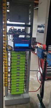
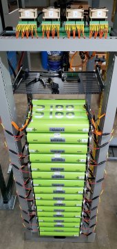
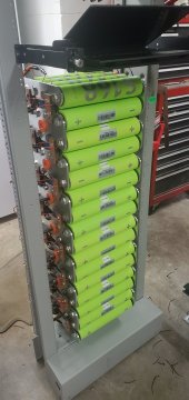
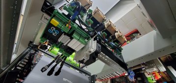
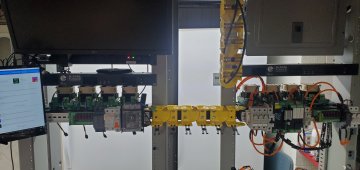
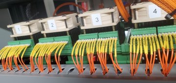
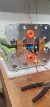
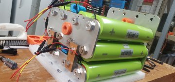
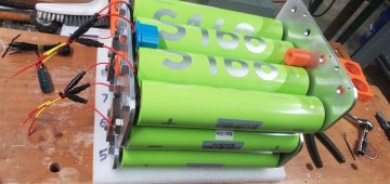
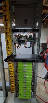
4 Batrium K9's monitoring 64 60280 cells on this 4P16S battery. First of Four batteries to build in 4 individual seismic racks. Progress pics attached.

Meanwell 12v Step down from 48v to run 4 Noctua fans relayed into batrium expansion board for heatsink cooling during bypass.

Im no expert on the batrium circuitry on the DIN Rail so if you see I need to make a modification I'd appreciate your opinions.

I also figured out how to cross reference a new 48v Shunt for a new Eaton Industrial Circuit breaker rather than doing the used ABB breaker.
20211119_194221.jpg
20211106_065829.jpg
20211105_014659.jpg
20211105_014236.jpg
20211102_220902.jpg
20211028_031623.jpg
20211028_031744.jpg
 
Wow! Those are some huge cylindrical cells!
Looks so clean!

Can you share your cross reference for the Eaton breaker? I'd love to get something similar.

What are the yellow things stacked up vertically on the one side of the rack?

I'm a bit confused on your series/parallel and BMS set up.

It looks like you have a single 16s4p battery. Then you connected 4 BMS modules to the 4 paralleled cell columns.

You've got all the columns paralleled at the cell level, so you don't need a BMS module on each. One 16s BMS would do the job of monitoring and balancing all cells. (Your set up would work great with a single K9)
 
Thank You!

The yellow things stacked up are Telect Wiretrax Wire management. I'm splitting them up and using them in short runs from rack to rack for the K9 module harness.20211128_195036.jpg

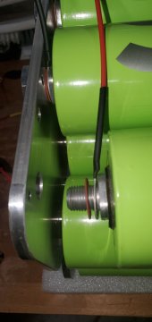
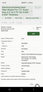
Yes I have the busbars at cell level on the outside of the Busbar but I have a fiber washer on the inside on the busbar between busbar and ring terminal to isolate the voltage and see exact individual cell readings. Took some thinking but I figured it out. Now the BMS can monitor exact cell readings and I can see all 64 cells individually and when a cell goes wack I can see exactly which one needs to be replaced if faulty.

And hey if a K9 goes out I've got plenty extra to make up for the loss haha. Just a redundancy configuration if parts become impossible to get in the future.

Eaton breaker and shunt info in the description of my vid.
 
Last edited:
So cool - thank you for sharing the pics.

Looks like 64 of them - e.g. 220ah @ 48v, about 11kwh. Looks like you're monitoring each individual cell (I see 64 blue bars on Batrium app) - which makes me think you have 4 x 16s1p... instead of 16s4p but the busbars look like you have 16s4p.

If I'm understanding the setup - what lead you to monitor each cell as apposed each parallel group of cells?

Will you be expanding the system?
 
Last edited:
No problem! I enjoy the feedback!

Yes the 64 cells are for the one 48v battery. The busbars are setup as 4p16S but I have each K9 module setup as 1P16S, as why I have 4 K9's to monitor the cells individually. The way I have the cells wired on the inside of the Busbar allows me to achieve this. I'll take photos on how Im isolating the cells from the inside of the Busbar tonight.

I could run one 16s module for the entire battery but then I would not be able to monitor every cell individually. I want to keep this system as healthy as possible and to do that I want to be very precise in the balancing and monitoring and replaces faulty cells. This way the Batrium BMS will tell me exactly which cell to Target. You can see by this photo how I'm labeling the cells to identify cell location easily. 20211128_203145.jpg

One rack done I'm starting on my second rack and I have 4 seismic heavy duty gauge steel racks. I have 256 cells.
 
Yes I have the busbars at cell level on the outside of the Busbar but I have a fiber washer on the inside on the busbar between busbar and ring terminal to isolate the voltage and see exact individual cell readings.

Maybe I'm not picturing it correctly, but either there are 4 cells in parallel or not. As far as I can tell the bus bars are going to put 4 cells in parallel. Fiber washer between the bus bars and cells just means a poor connection. The current must flow through the bolts and up to the head of the bolt to get to the bus bar and through the circuit.

In the images where you show the Batrium screen, I can see cell 13 on each K9 is high and 14-15 are slightly above average. That's either odd luck, or you have all 4 K9s monitoring the exact same thing.

Still good looking set up!
 
I could run one 16s module for the entire battery but then I would not be able to monitor every cell individually. I want to keep this system as healthy as possible and to do that I want to be very precise in the balancing and monitoring and replaces faulty cells.
If I may comment, just to advance the discussion.... I have 84 packs of 260ah each in 6 x 14s 18650 and use Batrium myself :)

With 4p, I don't see how you can tell anything about individual cells as the parallization will force all 4 cells to share the exact same voltage all the time. If one cell starts self-discharging (or something like that) you won't be able to tell which 1 of the 4. The only advantage I can see is quadrupling the balance current - but at only 220ah per 4p its not needed.
 
Maybe I'm not picturing it correctly, but either there are 4 cells in parallel or not. As far as I can tell the bus bars are going to put 4 cells in parallel. Fiber washer between the bus bars and cells just means a poor connection. The current must flow through the bolts and up to the head of the bolt to get to the bus bar and through the circuit.

In the images where you show the Batrium screen, I can see cell 13 on each K9 is high and 14-15 are slightly above average. That's either odd luck, or you have all 4 K9s monitoring the exact same thing.

Still good looking set up!
Thank You! Yes 4 cells in parallel, each of those 4 cells are on different K9 modules as I have 4 rows of 16 cells. As why you see 4 high cells. I let the BMS do it's magic and it pulled those high cells individually down to match the rest of the cells. Everything went smooth on that test.
 
If I may comment, just to advance the discussion.... I have 84 packs of 260ah each in 6 x 14s 18650 and use Batrium myself :)

With 4p, I don't see how you can tell anything about individual cells as the parallization will force all 4 cells to share the exact same voltage all the time. If one cell starts self-discharging (or something like that) you won't be able to tell which 1 of the 4. The only advantage I can see is quadrupling the balance current - but at only 220ah per 4p its not needed.
Yes it forces all 4 cells to share the same overall voltage from the busbar to terminal nut. With the way I isolated the BMS lead for each cell seperate from the busbar on the inside of the terminal to cell area allows me to isolate voltage oddly enough. It sounds different I agree but it seems to be working flawlessly. I'll take pics in a minute while I'm building this new battery to show you what I mean ?
 
Thank You!

The yellow things stacked up are Telect Wiretrax Wire management. I'm splitting them up and using them in short runs from rack to rack for the K9 module harness.View attachment 73806

Yes I have the busbars at cell level on the outside of the Busbar but I have a fiber washer on the inside on the busbar between busbar and ring terminal to isolate the voltage and see exact individual cell readings. Took some thinking but I figured it out. Now the BMS can monitor exact cell readings and I can see all 64 cells individually and when a cell goes wack I can see exactly which one needs to be replaced if faulty.

And hey if a K9 goes out I've got plenty extra to make up for the loss haha. Just a redundancy configuration if parts become impossible to get in the future.

Eaton breaker and shunt info in the description of my vid.
I like the idea of the 48V shunt trip but why not just use the Challenger breaker?

As for the ABB, rated to 600VAC, the Eaton is rated at 240VAC. Breaking DC high volts is considerably harder than AC. The Cutler Hammer HFD series is rated 600VAC and 250VDC. I haven't found if ABB carries any VDC rating.

The ABB TMAX is the newer version, might be a better choice than the ABB, I'm still pondering what I'll use.
Awesome point, I'm going to look into this more! I do have a new challenger breaker. The Eaton had a higher amp rating than my Challenger breaker I swapped out the shunt trip to the Eaton.
 
Yes it forces all 4 cells to share the same overall voltage from the busbar to terminal nut. With the way I isolated the BMS lead for each cell seperate from the busbar on the inside of the terminal to cell area allows me to isolate voltage oddly enough. It sounds different I agree but it seems to be working flawlessly. I'll take pics in a minute while I'm building this new battery to show you what I mean ?

If I may comment, just to advance the discussion.... I have 84 packs of 260ah each in 6 x 14s 18650 and use Batrium myself :)

With 4p, I don't see how you can tell anything about individual cells as the parallization will force all 4 cells to share the exact same voltage all the time. If one cell starts self-discharging (or something like that) you won't be able to tell which 1 of the 4. The only advantage I can see is quadrupling the balance current - but at only 220ah per 4p its not needed.
20211128_215215.jpg20211128_220614.jpg20211128_220511.jpgScreenshot_20211128-224339_McMaster.jpg20211128_220554.jpg
 
Not sure if this is the most elaborate troll post of all time, or if you actually think those BMS sense leads are isolated.

Either way, it’s super impressive!
? I feel you! And Thank You, I greatly appreciate it!

It is the only way I could wire the BMS leads for the Batrium to get a precise cell level reading and treat each cell individually with monitoring and balancing without forced interference from the busbar voltage. This has worked like a charm, oddly enough. I did not top balance, Initially I had a handful of cells around 3.3v with the lowest cell around 2.7v. I brought the bypass temporarily down to 2.6v, and it did pull all cells to 2.6, obviously it did take a little longer for K9's to bleed off the higher 3.3v cells but the batrium did work it's magic on those that were higher and pulled them down to 2.6 with their buddies, and all cells are now in sync.
 
I'm trying to understand how it reads individual cell voltage if there is continuity thru the stud and nut to the busbar. I'm certainly not a fan of pushing current thru threads, you may find down the road you can't remove the nut. The arcing across the threads creates a "super locknut".

You have to understand that in order for the individual cell voltage to be read, there has to be resistance in the circuit. The thread connection is that resistance.

It's impressive, but leaves many questions.......
 
You have to understand that in order for the individual cell voltage to be read, there has to be resistance in the circuit. The thread connection is that resistance.
Preferably infinite resistance

He is definitely measuring individual cell voltages (well, sort of, the voltage drop due to the bus bar always distorts the real voltage due to the way a BMS connects to series sets) but creating a poor connection to the bus bar and there will never be much drift between parallel cells because they are still connected through the bus bar so they are constantly balancing with the other cells in the parallel set, you won't see an individual cell discharge faster or slower than other cells in a parallel set so he is fooling himself into thinking he will be able to detect an individual bad/weak cell. A weak cell will just reduce the capacity of a parallel set so that set will get out of balance with other sets that are in series with it.
I never said I'm an expert so I'm definitely not trying to fool myself as why I posted this thread to get everyone's opinion. While doing a bypass set at 2.6v, Why did the Batrium K9 hold all cells at 2.6v while the handful of cells that were above 3.3 bled down to 2.6 individually until all cells were in sync? Thank You for your input
 
I'm trying to understand how it reads individual cell voltage if there is continuity thru the stud and nut to the busbar. I'm certainly not a fan of pushing current thru threads, you may find down the road you can't remove the nut. The arcing across the threads creates a "super locknut".

You have to understand that in order for the individual cell voltage to be read, there has to be resistance in the circuit. The thread connection is that resistance.

It's impressive, but leaves many questions.......
I agree many questions for me too as why I'm loving everyone's sincere input. This is all trial and error for me. I'm doing the best I can for what I have taught myself. I won't be pulling tons of current through these batteries so I would assume the odds of thread lock wouldnt be that high risk. One would hope heh heh
 
I never said I'm an expert so I'm definitely not trying to fool myself as why I posted this thread to get everyone's opinion. While doing a bypass set at 2.6v, Why did the Batrium K9 hold all cells at 2.6v while the handful of cells that were above 3.3 bled down to 2.6 individually until all cells were in sync? Thank You for your input
I wasn't there so I don't know what your test looked like but if you have cells that are at 2.6V connected in parallel to cells at 3.3V via the bus bar you showed a picture of then you would get a very large rush of current and the voltages would equalize very quickly. But it is really fundamentally impossible for cells connected in parallel via a bus bar to get to such dramatically different voltages in the first place so I just find it difficult to believe you are getting those measurements from two cells connected in parallel or you aren't measuring what you think you are measuring.
 
I agree many questions for me too as why I'm loving everyone's sincere input. This is all trial and error for me. I'm doing the best I can for what I have taught myself. I won't be pulling tons of current through these batteries so I would assume the odds of thread lock wouldnt be that high risk. One would hope heh heh
The problem is you have a group of cells connected on a busbar, so any readings you're getting at the cell won't be accurate. There is some voltage drop present or otherwise all the readings would be the same volts.

As to why you saw the initial cell voltage on some cells at 2.6V and some at 3.3V is because you didn't top balance them in parallel. The higher voltage cells will bleed off to the lower voltage cells once the busbar connected all the cells. The Batrium probably had nothing to do with it.

Take this photo for instance. I see a group of 4 cells with the + on one end all connected to the busbar. That puts the cells in parallel. The cells will balance with each other, no different than top balancing in parallel.
20211128_220511-jpg.73821


As for the nut welding on the stud, as long as current is passing thru the threads, you will find arcing. If you have ever used an arc welder and used the outside of a nut to connect the negative cable, you will find the current passing thru the threads has welded the nut solid to the stud or bolt. The reason is the arcing that occurs, threads are not perfect mating surfaces and thus there is resistance and arcing. Two things occur, mini arcs just like the arc welder and excessive heating of the threads on both surfaces leading to distortion.

Have you loaded the cells down and test capacity? Results will probably be all over the place as the voltage drop/resistance across the terminals won't be even.
Thank You for explaining that, this makes more sense to me now. I have not loaded the cells down and capacity tested. One I do this I will update my findings ? ?
 
I wasn't there so I don't know what your test looked like but if you have cells that are at 2.6V connected in parallel to cells at 3.3V via the bus bar you showed a picture of then you would get a very large rush of current and the voltages would equalize very quickly. But it is really fundamentally impossible for cells connected in parallel via a bus bar to get to such dramatically different voltages in the first place so I just find it difficult to believe you are getting those measurements from two cells connected in parallel or you aren't measuring what you think you are measuring.
I see what you mean, Thank You for explaining that; only other option is to tear everything back down and rebuild with one K9 and leads placed on outside of busbar. Once I get this second battery online and synced with the other I'll run tests and come to a conclusion. Trial and error...and labor ?
 

diy solar

diy solar
Back
Top