I wasn't there so I don't know what your test looked like but if you have cells that are at 2.6V connected in parallel to cells at 3.3V via the bus bar you showed a picture of then you would get a very large rush of current and the voltages would equalize very quickly. But it is really fundamentally impossible for cells connected in parallel via a bus bar to get to such dramatically different voltages in the first place so I just find it difficult to believe you are getting those measurements from two cells connected in parallel or you aren't measuring what you think you are measuring.I never said I'm an expert so I'm definitely not trying to fool myself as why I posted this thread to get everyone's opinion. While doing a bypass set at 2.6v, Why did the Batrium K9 hold all cells at 2.6v while the handful of cells that were above 3.3 bled down to 2.6 individually until all cells were in sync? Thank You for your input


You are using an out of date browser. It may not display this or other websites correctly.
You should upgrade or use an alternative browser.
You should upgrade or use an alternative browser.
48v 64 cell SAB 60280 Batrium K9 Rack Build
- Thread starter Gr00ldude48
- Start date
Zwy
Solar Wizard
The problem is you have a group of cells connected on a busbar, so any readings you're getting at the cell won't be accurate. There is some voltage drop present or otherwise all the readings would be the same volts.I agree many questions for me too as why I'm loving everyone's sincere input. This is all trial and error for me. I'm doing the best I can for what I have taught myself. I won't be pulling tons of current through these batteries so I would assume the odds of thread lock wouldnt be that high risk. One would hope heh heh
As to why you saw the initial cell voltage on some cells at 2.6V and some at 3.3V is because you didn't top balance them in parallel. The higher voltage cells will bleed off to the lower voltage cells once the busbar connected all the cells. The Batrium probably had nothing to do with it.
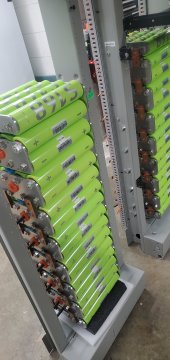
Take this photo for instance. I see a group of 4 cells with the + on one end all connected to the busbar. That puts the cells in parallel. The cells will balance with each other, no different than top balancing in parallel.
As for the nut welding on the stud, as long as current is passing thru the threads, you will find arcing. If you have ever used an arc welder and used the outside of a nut to connect the negative cable, you will find the current passing thru the threads has welded the nut solid to the stud or bolt. The reason is the arcing that occurs, threads are not perfect mating surfaces and thus there is resistance and arcing. Two things occur, mini arcs just like the arc welder and excessive heating of the threads on both surfaces leading to distortion.
Have you loaded the cells down and test capacity? Results will probably be all over the place as the voltage drop/resistance across the terminals won't be even.
Gr00ldude48
New Member
- Joined
- Jul 6, 2021
- Messages
- 92
Thank You for explaining that, this makes more sense to me now. I have not loaded the cells down and capacity tested. One I do this I will update my findings ? ?The problem is you have a group of cells connected on a busbar, so any readings you're getting at the cell won't be accurate. There is some voltage drop present or otherwise all the readings would be the same volts.
As to why you saw the initial cell voltage on some cells at 2.6V and some at 3.3V is because you didn't top balance them in parallel. The higher voltage cells will bleed off to the lower voltage cells once the busbar connected all the cells. The Batrium probably had nothing to do with it.
Take this photo for instance. I see a group of 4 cells with the + on one end all connected to the busbar. That puts the cells in parallel. The cells will balance with each other, no different than top balancing in parallel.
As for the nut welding on the stud, as long as current is passing thru the threads, you will find arcing. If you have ever used an arc welder and used the outside of a nut to connect the negative cable, you will find the current passing thru the threads has welded the nut solid to the stud or bolt. The reason is the arcing that occurs, threads are not perfect mating surfaces and thus there is resistance and arcing. Two things occur, mini arcs just like the arc welder and excessive heating of the threads on both surfaces leading to distortion.
Have you loaded the cells down and test capacity? Results will probably be all over the place as the voltage drop/resistance across the terminals won't be even.
Gr00ldude48
New Member
- Joined
- Jul 6, 2021
- Messages
- 92
I see what you mean, Thank You for explaining that; only other option is to tear everything back down and rebuild with one K9 and leads placed on outside of busbar. Once I get this second battery online and synced with the other I'll run tests and come to a conclusion. Trial and error...and labor ?I wasn't there so I don't know what your test looked like but if you have cells that are at 2.6V connected in parallel to cells at 3.3V via the bus bar you showed a picture of then you would get a very large rush of current and the voltages would equalize very quickly. But it is really fundamentally impossible for cells connected in parallel via a bus bar to get to such dramatically different voltages in the first place so I just find it difficult to believe you are getting those measurements from two cells connected in parallel or you aren't measuring what you think you are measuring.
400bird
Solar Wizard
I'd recommend removing those insulating washers before putting an more loads on the system. If you weld nuts/studs does that ruin the cell?
I'd also tap a dedicated hole in each bus bar for the balance lead.
I'd also tap a dedicated hole in each bus bar for the balance lead.
Gr00ldude48
New Member
- Joined
- Jul 6, 2021
- Messages
- 92
Yes I definitely don't want to weld anything! I designed the busbars to have dedicated threaded holes for the balance lead just incase so thats a win.I'd recommend removing those insulating washers before putting an more loads on the system. If you weld nuts/studs does that ruin the cell?
I'd also tap a dedicated hole in each bus bar for the balance lead.
Gr00ldude48
New Member
- Joined
- Jul 6, 2021
- Messages
- 92

At least itll look like a pretty ornament if I welded everything together. But Thanks to everyone's input I may not have just an ornament heh heh
Gr00ldude48
New Member
- Joined
- Jul 6, 2021
- Messages
- 92
K tore the current battery build back down, removed all the fiber washers, bolted everything back nice and tidy, was so lovely not having to fidget with all those leads while building the battery. Installed battery in rack.
Next step is wiring BMS leads to holes I originally had tapped in each busbar specifically for BMS leads.
Next step is wiring BMS leads to holes I originally had tapped in each busbar specifically for BMS leads.
Attachments
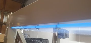
Very attractive use of components, and a lot of effort on your part. Overall, I distrust any system whereby a dropped wrench, or a piece of metal such as a wedding ring could cause a massive arc. When I work on cells on my bench-top, I always cover terminals with a piece of heavy cardboard and some temporary tape just in case. By the way, kudos for a clean work-space!
I'd incorporate some clear Lexan shields into your project when you have the final configuration worked out.
I'd incorporate some clear Lexan shields into your project when you have the final configuration worked out.
Gr00ldude48
New Member
- Joined
- Jul 6, 2021
- Messages
- 92
Thank You! I concur, I was definitely planning on fabricating shields, I did this with my previous system too once a figured out the wiring schematics. I've got some cool ideas ?Very attractive use of components, and a lot of effort on your part. Overall, I distrust any system whereby a dropped wrench, or a piece of metal such as a wedding ring could cause a massive arc. When I work on cells on my bench-top, I always cover terminals with a piece of heavy cardboard and some temporary tape just in case. By the way, kudos for a clean work-space!
I'd incorporate some clear Lexan shields into your project when you have the final configuration worked out.
Attachments
alvirtuoso
New Member
- Joined
- Sep 28, 2021
- Messages
- 81
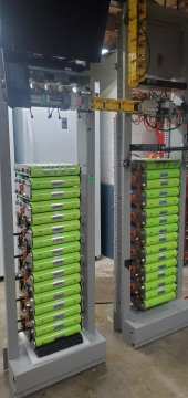
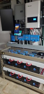
Does your batrium communicates with your Growatt?4 Batrium K9's monitoring 64 60280 cells on this 4P16S battery. First of Four batteries to build in 4 individual seismic racks. Progress pics attached.
Meanwell 12v Step down from 48v to run 4 Noctua fans relayed into batrium expansion board for heatsink cooling during bypass.
Im no expert on the batrium circuitry on the DIN Rail so if you see I need to make a modification I'd appreciate your opinions.
I also figured out how to cross reference a new 48v Shunt for a new Eaton Industrial Circuit breaker rather than doing the used ABB breaker.
View attachment 73635
View attachment 73636
View attachment 73637
View attachment 73638
View attachment 73639
View attachment 73640
View attachment 73641
Gr00ldude48
New Member
- Joined
- Jul 6, 2021
- Messages
- 92
Havent got that far yet, not sure how many resources/support is online for the Batrium to communicate with the Growatt. We will see ?Does your batrium communicates with your Growatt?
Maintenance guy
New Member
I am so glad you removed those fiber washers as these cells were not designed to be mounted that way. @ 110 amp per cell capable i am glad you changed your mind.
Beautiful set up capable of 440 amps @ 48 volts, very nice.
Beautiful set up capable of 440 amps @ 48 volts, very nice.
Last edited:
Gr00ldude48
New Member
- Joined
- Jul 6, 2021
- Messages
- 92
Thank You! Finished Second battery, built without fiber washer last night, tore down first battery today and took out fiber washers and rewired leads. Put second battery online today after wiring the DIN rail hardware. Keeping the First battery offline until I get the second battery down to the same voltage as the first then I'll bring them up together. I have two more battery racks to build after these two ? Should be a beauty! I'll clean up wire routes once I get everything in the final position.I am so glad you removed those fiber washers as these cells were not designed to be mounted that way. @ 110 amp per cell capable i am glad you changed your mind.
Beautiful set up capable of 440 amps @ 48 volts, very nice.

sunshine_eggo
Happy Breffast!
Thank You!
Yes I have the busbars at cell level on the outside of the Busbar but I have a fiber washer on the inside on the busbar between busbar and ring terminal to isolate the voltage and see exact individual cell readings. Took some thinking but I figured it out. Now the BMS can monitor exact cell readings and I can see all 64 cells individually and when a cell goes wack I can see exactly which one needs to be replaced if faulty.
And hey if a K9 goes out I've got plenty extra to make up for the loss haha. Just a redundancy configuration if parts become impossible to get in the future.
Eaton breaker and shunt info in the description of my vid.
You have constructed a most luscious nightmare. I truly mean that in a positive way. I'm glad I made it through to the end of the thread and see that you've removed the washers.
If someone mentioned it already, I apologize, but you can still get individual cell monitoring simply by treating each column of cells as individual batteries only paralleled at the end terminals:

On the opposite side, you could cut it from top to bottom.
Basically cut there between each column to isolate each. I realize that's going to make suspending them a challenge, but if you want to retain individual cell monitoring, it's an option.
Gr00ldude48
New Member
- Joined
- Jul 6, 2021
- Messages
- 92
Much appreciated advice, no one has mentioned that thus far; so Thank You! I do understand your suggestion; suspending that properly would be intense... an engineering feat haha. But I guess that wouldn't be but a bit more brainwork on the CAD software for the CNC. Sounds like a fun challenge to tackle. Once I get this all up and running I'll see what I can come up with. How would you suggest running the Batrium leads for individual monitoring?You have constructed a most luscious nightmare. I truly mean that in a positive way. I'm glad I made it through to the end of the thread and see that you've removed the washers.
If someone mentioned it already, I apologize, but you can still get individual cell monitoring simply by treating each column of cells as individual batteries only paralleled at the end terminals:
View attachment 74452
On the opposite side, you could cut it from top to bottom.
Basically cut there between each column to isolate each. I realize that's going to make suspending them a challenge, but if you want to retain individual cell monitoring, it's an option.
sunshine_eggo
Happy Breffast!
Hmm...
It appears to me that the terminals of the bottom cells are supporting the entire column above and then the bottom barrel of the cell supporting everything? If that's the case, I would be concerned about the terminals' longevity. Since you've already established the bottom barrel as being sufficiently strong to support the whole column, I would explore spacers between cells and then using the phenolic blocks to join the columns where cut for improved stability.
NVM: I assume the posts and orange discs are the supports now that I look at the other one.
Last edited:
sunshine_eggo
Happy Breffast!
Much appreciated advice, no one has mentioned that thus far; so Thank You! I do understand your suggestion; suspending that properly would be intense... an engineering feat haha. But I guess that wouldn't be but a bit more brainwork on the CAD software for the CNC. Sounds like a fun challenge to tackle. Once I get this all up and running I'll see what I can come up with. How would you suggest running the Batrium leads for individual monitoring?
CAD? CNC? Pfft. Die grinder or chop saw, several wheels, and an afternoon.
")
I have often spent many hours more time exploring options in Solidworks than it would have taken me to fix it in the real world. Watch out for that...
Gr00ldude48
New Member
- Joined
- Jul 6, 2021
- Messages
- 92
I 3D printed blue bushings that fit between every row of cells and orange bushings that 5/8 threaded steel rods run through the server rack and busbar to support the weight. The bottom cells are suspended mid air and touch nothing ? The foam pad was temporary to get initial height for when I put my first support rod In. Yes I also like the phenolic block idea to join columns!Hmm...
It appears to me that the terminals of the bottom cells are supporting the entire column above and then the bottom barrel of the cell supporting everything? If that's the case, I would be concerned about the terminals' longevity. Since you've already established the bottom barrel as being sufficiently strong to support the whole column, I would explore spacers between cells and then using the phenolic blocks to join the columns where cut for improved stability.
NVM: I assume the posts and orange discs are the supports now that I look at the other one.


I scrapped this wiring idea just showing the bushings for cell support. I made sure everything is within thousands of an inch in Accuracy to get maximum support. I gave the busbar terminal holes a bit of extra leeway for mounting ease. But when I bolt up the busbar support blocks it pulls everything square due to the bushing placement and size.
Gr00ldude48
New Member
- Joined
- Jul 6, 2021
- Messages
- 92
Chuckles** I feel you on that one! I only need a food break when working in the garage, I need a triathlon to expend the frustration built up from what that software does to me at times ?CAD? CNC? Pfft. Die grinder or chop saw, several wheels, and an afternoon.
I have often spent many hours more time exploring options in Solidworks than it would have taken me to fix it in the real world. Watch out for that...
Similar threads
- Replies
- 18
- Views
- 959