You have constructed a most luscious nightmare. I truly mean that in a positive way. I'm glad I made it through to the end of the thread and see that you've removed the washers.
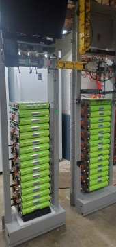
If someone mentioned it already, I apologize, but you can still get individual cell monitoring simply by treating each column of cells as individual batteries only paralleled at the end terminals:
View attachment 74452
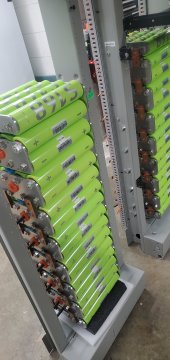
On the opposite side, you could cut it from top to bottom.
Basically cut there between each column to isolate each. I realize that's going to make suspending them a challenge, but if you want to retain individual cell monitoring, it's an option.


")


