diy solar

diy solar

Signature Solar EG4 6.5K Off-Grid Inverter | 6500EX-48

Sure, but loading 6600w on one leg, and 3000w on another is an overload here.

Where in a sol-ark I believe it's the IMBALANCE that matters. So on a 15k you can do 8000 on one and 2500 on another and that's ok
The LV6548s will allow a full 6500w on one leg (inverter), and 0w on the 2nd leg (inverter). The Sol-Ark, from what I have read, cannot do this.

I have personally tested this with 2x MPP LV6548s that I have. Im assuming the EG4 is the same.

I know lots of bouncing around lol. My mistake for not using the proper naming.

Edit: i will say I probably wouldn't load my LV6548s at more than 60-70% load continuously, as they get murder hot and require either lots of ventilation, or air conditioning. I opted to air condition the compartment that my 2x LV6548s are in.
 
Heat. I never even thought of that. Will two of these be ok running in an unconditioned garage with summer getting up to about 92 in there sometimes?. I plan to put the two inverters, load center, wiring, etc, just like Will's set up on the wall in the detached garage running 2224 alum 150 feet underground to my transfer panel in the house. In effect taking the place of my 12k generator. The generator will still be available though.
 
That thread started off talking about a 240V output inverter, not a 120V inverter.

It's a pair of LV6548's, each one is 120V.


I'm not going to read 26 pages, but please, do not confound two different issues. The EG4 is a 120V inverter with a grounded neutral, not a 240V inverter like the MPP was, with a grounded neutral as is done for Europe, (TUV).
If you read the 26 pages of this thread which covers the LV6548 you might have understood why this is important. https://diysolarforum.com/threads/mpp-lv6548-ground-neutral-safety.36241/

The EG4 is basically the same as the LV6548 and it handles N-G bond the exact same manner. N-G are bonded under inverter operation. One could remove the ground screw such as Will did in his video on the EG4. Both are 120V inverters.

However, his install is completely off grid use only without any AC input. This is an important distinction. Thus he can bond N-G in a service panel after the inverters which I still don't believe is a great idea and it also voids the warranty unless Signature Solar is promoting screw removal. I hope you're following along as this changes with AC input. With AC input, N-G bond occurs at the main service panel and by code the first service panel after the meter. This puts bonding at 2 locations with N-G bond in the inverter and main service panel. This creates an issue with objectionable current on G unless a 3 pole transfer switch is used where neutral is switched.


That configuration is an issue because in the US, it is the center-leg of the Split phase that is grounded, not the L2 side of the 240V circuit. The EG4 is different, nobody is going to have that problem here because it isn't 240V output.

Tell ya what, I'm going to let you do your thing and set it up the way you think it should be. When you're done, measure current on G under inverter power. Good luck.
 
It's a pair of LV6548's, each one is 120V.


If you read the 26 pages of this thread which covers the LV6548 you might have understood why this is important. https://diysolarforum.com/threads/mpp-lv6548-ground-neutral-safety.36241/

The EG4 is basically the same as the LV6548 and it handles N-G bond the exact same manner. N-G are bonded under inverter operation. One could remove the ground screw such as Will did in his video on the EG4. Both are 120V inverters.

However, his install is completely off grid use only without any AC input. This is an important distinction. Thus he can bond N-G in a service panel after the inverters which I still don't believe is a great idea and it also voids the warranty unless Signature Solar is promoting screw removal. I hope you're following along as this changes with AC input. With AC input, N-G bond occurs at the main service panel and by code the first service panel after the meter. This puts bonding at 2 locations with N-G bond in the inverter and main service panel. This creates an issue with objectionable current on G unless a 3 pole transfer switch is used where neutral is switched.


Tell ya what, I'm going to let you do your thing and set it up the way you think it should be. When you're done, measure current on G under inverter power. Good luck.
If I'm understanding this correctly. .. In a grid supported split phase setup could you remove the bonding screw from both inverters safely and wire this way? meter; main distribution panel (neutral bonded from main); EG4 in fed from distribution panel; EG4 out to main house panel? All N G bonds removed except the main distribution panel that is only supporting the EG4 if needed.
 

Attachments

  • Screenshot_20220529-201139.jpg
    Screenshot_20220529-201139.jpg
    203.5 KB · Views: 28
If I'm understanding this correctly. .. In a grid supported split phase setup could you remove the bonding screw from both inverters safely and wire this way? meter; main distribution panel (neutral bonded from main); EG4 in fed from distribution panel; EG4 out to main house panel? All N G bonds removed except the main distribution panel that is only supporting the EG4 if needed.
I think this would work. Only 1 common neutral/ground bond. Grounding conversations go in circles so much because of all the intricacies and differing opinions.
 
Ok, I've read thru this thread thoroughly because I am very interested in getting this inverter. I've posted my plans in this thread previously, so I won't rehash them here. My app will involve just one EG-4 6548, so I don't care about split phase/240V.

I initially won't have enough panels nor battery backup to go totally off grid with my 120V devices, but may add more of those items later, while keeping one inverter. So, saying that, I will need to be grid-tied in those situations where the panels and/or the batts won't be able to power my loads and/or charge the batts. I'm assuming that in bypass mode the inverter will still charge the batts, even though it's not "inverting"? Or am I wrong there?

So, my question is this-

Since the inverter will be in either a bypass/charge mode or an inverter mode, how do I resolve this ground-neutral bond issue with the inverter? I think the concensus here is that this bond inside the inverter is not desirable nor even really safe in this mode. So, do I remove the bonding screw inside the inverter, and potentially void my warranty? If not, what is the remedy? (And, no I can't afford a Sol-Ark..)
 
Last edited:
I think this would work. Only 1 common neutral/ground bond. Grounding conversations go in circles so much because of all the intricacies and differing opinions.
Thanks Richard. Yes most grounding conversations are one big loop ?.

What impact would removing the screw have on potential warranty claims?
 
It's a pair of LV6548's, each one is 120V.


If you read the 26 pages of this thread which covers the LV6548 you might have understood why this is important. https://diysolarforum.com/threads/mpp-lv6548-ground-neutral-safety.36241/

The EG4 is basically the same as the LV6548 and it handles N-G bond the exact same manner. N-G are bonded under inverter operation. One could remove the ground screw such as Will did in his video on the EG4. Both are 120V inverters.

However, his install is completely off grid use only without any AC input. This is an important distinction. Thus he can bond N-G in a service panel after the inverters which I still don't believe is a great idea and it also voids the warranty unless Signature Solar is promoting screw removal. I hope you're following along as this changes with AC input. With AC input, N-G bond occurs at the main service panel and by code the first service panel after the meter. This puts bonding at 2 locations with N-G bond in the inverter and main service panel. This creates an issue with objectionable current on G unless a 3 pole transfer switch is used where neutral is switched.


Tell ya what, I'm going to let you do your thing and set it up the way you think it should be. When you're done, measure current on G under inverter power. Good luck.
I'm an engineer who has been designing DC-AC inverters since the 1980's. I don't need luck. Thank you.
 
If I'm understanding this correctly. .. In a grid supported split phase setup could you remove the bonding screw from both inverters safely and wire this way? meter; main distribution panel (neutral bonded from main); EG4 in fed from distribution panel; EG4 out to main house panel? All N G bonds removed except the main distribution panel that is only supporting the EG4 if needed.
 
Ok, I've read thru this thread thoroughly because I am very interested in getting this inverter. I've posted my plans in this thread previously, so I won't rehash them here. My app will involve just one EG-4 6548, so I don't care about split phase/240V.

I initially won't have enough panels nor battery backup to go totally off grid with my 120V devices, but may add more of those items later, while keeping one inverter. So, saying that, I will need to be grid-tied in those situations where the panels and/or the batts won't be able to power my loads and/or charge the batts. I'm assuming that in bypass mode the inverter will still charge the batts, even though it's not "inverting"? Or am I wrong there?

So, my question is this-

Since the inverter will be in either a bypass/charge mode or an inverter mode, how do I resolve this ground-neutral bond issue with the inverter? I think the concensus here is that this bond inside the inverter is not desirable nor even really safe in this mode. So, do I remove the bonding screw inside the inverter, and potentially void my warranty? If not, what is the remedy? (And, no I can't afford a Sol-Ark..)
If you are using a single EG4 or LV6548, this won't be a problem because the transfer switch built into the unit will switch Neutral. The N-G bond is retained in the main service panel and a subpanel after the inverter handles the loads. No N-G bond in the subpanel. Do not remove the screw in the inverter, if you did, there would not be N-G bonding for fault protection.

With a single unit, there won't be any parallel paths.
 
I think this would work. Only 1 common neutral/ground bond. Grounding conversations go in circles so much because of all the intricacies and differing opinions.
The reason for differing opinions is either ignorance or financial/being cheap.

There is a right way and a wrong way. If you don't believe me, go ask @FilterGuy
 
If I'm understanding this correctly. .. In a grid supported split phase setup could you remove the bonding screw from both inverters safely and wire this way? meter; main distribution panel (neutral bonded from main); EG4 in fed from distribution panel; EG4 out to main house panel? All N G bonds removed except the main distribution panel that is only supporting the EG4 if needed.
That is not the grounding screw that the folks are talking about. It is a screw inside the inverter that disconnects that path that the internal bonding relay uses to bond Neutral to ground. Unfortunately, EG4 and MPP do not document it in the manual.
 
Intimately, and there won't be any if done correctly with "this" EG4 inverter, unlike the 240V MPP's made for Europe.
You should probably study all of inverters from Growatt and MPP that are made by Voltronics, the same company producing the EG4.

This discussion has nothing to do with the SPF5000 made for the Euro market.
 
Oh I believe you. I just don't have the energy to go through this argument on the forums daily haha
Richard, I have been making an assumption that I can't verify in the 6548 manual. My assumption is, that when the DC-AC inverter is operating, the N-G bond is present inside the inverter and the Input N is isolated from the Output N by a relay. When the inverter is in Bypass mode, then the N is passed straight through and the N-G bond inside the inverter is bypassed and not connected to the output N. (i.e., the Inverter N is separate from the input N.) That is how I design inverters to avoid "parallel paths".

Since there is no 1-Line diagram or Schematic in the manual, showing that the N is switched by a relay, then @Zwy may be right. Can you confirm one way or the other, please? I would think my assumption is correct because that is how I've engineered them in the past, and I would also assume that is why the N-G bond is inside the inverter and not at the output terminal. If it were at the output terminal, then it could not be bypassed as it needs to be, to avoid parallel paths.

Thank you.
 
Last edited:
Richard, I have been making an assumption that I can't verify in the 6548 manual. My assumption is, that when the DC-AC inverter is operating, the N-G bond is present inside the inverter and the Input N is isolated from the Output N by a relay. When the inverter is in Bypass mode, then the N is passed straight through and the N-G bond inside the inverter is bypassed and not connected to the output N. (i.e., the Inverter N is separate from the input N.) That is how I design inverters to avoid "parallel paths".

That is how it is wired internally. Members already contacted MPP and Growatt and recieved confirmation in emails.
Since there is no 1-Line diagram or Schematic in the manual, showing that the N is switched by a relay, then @Zwy may be right. Can you confirm one way or the other, please?

It should have been documented in the manuals, but it isn't.
I would think my assumption is correct because that is how I've engineered them in the past, and I would also assume that is why the N-G bond is inside the inverter and not at the output terminal. If it were at the output terminal, then it could not be switched as it needs to be, to avoid parallel paths.

Thank you.
These will work perfectly fine with a single inverter putting out 120V. I have a Growatt SPF3000 on my truck camper, it works great, no problems with N-G bonding.

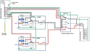
The issue is split phase operation with an N running from each inverter plus a G. This is how I intend to wire my 2 LV6548's after the numerous discussions on this forum over many threads. There will be objectionable current between both inverters on G, I do not intend to remove a screw in one inverter at this time. Daisy chain #2.jpg
 
That is how it is wired internally. Members already contacted MPP and Growatt and recieved confirmation in emails.


It should have been documented in the manuals, but it isn't.

These will work perfectly fine with a single inverter putting out 120V. I have a Growatt SPF3000 on my truck camper, it works great, no problems with N-G bonding.

The issue is split phase operation with an N running from each inverter plus a G. This is how I intend to wire my 2 LV6548's after the numerous discussions on this forum over many threads. There will be objectionable current between both inverters on G, I do not intend to remove a screw in one inverter at this time. View attachment 96414
I see what you're saying now. When connected in split-phase or in parallel, you end up with multiple N-G bonds, one inside each inverter, resulting in parallel paths to ground. There's a good argument in this for 240V inverters with split-phase isolation transformers at the output, which won't have this issue. The load current coming back on the N for an unbalanced load gets split, and when it returns to the wrong inverter it has to pass through the ground bond to balance the circuit. Not good. Worse, if you remove the screw in both inverters and have an N-G bond at the sub-panel, then when it switches to Bypass, there will be two N-G bonds again with parallel paths back to the MSP.

I will note however, Ground current between the two inverters is not a code violation or a concern for UL as long as the bond is secure and low resistance, and the ground wire is sized the same as the N. Then there is no hazard of electric shock while everything is connected. The shock hazard occurs when one of the inverters is not grounded, then a potential could build up between them, which is (probably?) what Will saw when he only removed the ground screw from one inverter.
 
Last edited:
Looking for some assistance. I'd like to state the following.. this is my first solar project.... I may be an idiot. I purchased the 6500ex-48 from signature solar. I connected solar and ac in. I would like to use solar priority then grid to power the load. I can't seem to tell if I have this working. I do not have a battery connected as I plan to in the future. My goal was to simply reduce my kwh used from the grid during the day. When the inverter is powered on it shows a warning flash in the upper left of BP and the display shows bypass. I cannot seem to get this off of bypass, which I am under the impression is simply powering the load from the grid?
 
Looking for some assistance. I'd like to state the following.. this is my first solar project.... I may be an idiot. I purchased the 6500ex-48 from signature solar. I connected solar and ac in. I would like to use solar priority then grid to power the load. I can't seem to tell if I have this working. I do not have a battery connected as I plan to in the future. My goal was to simply reduce my kwh used from the grid during the day. When the inverter is powered on it shows a warning flash in the upper left of BP and the display shows bypass. I cannot seem to get this off of bypass, which I am under the impression is simply powering the load from the grid?
How to control it from the front display is all in the manual. To offer assistance, however, we need to know what the input voltage is from your solar panels. Is the voltage within the operating MPPT range of the inverter, and can it produce enough DC watts to operate it with the load you have connected?
 
Thanks. I even liked the post the other day, I read to much....
I'm still confused how you could have 2 bonds with both screws removed.
Wouldn't the neutral (bonded at the main panel) just pass through the inverters if both bonding screws are removed?
 
I am showing 200 volts from the panels
You know, I'm looking through the manual and the "Basic Setup" shows a 48V battery connected, and I don't see anywhere, where it says that this inverter can operate without a battery attached. Is anyone certain this is possible? I've only ever seen this inverter used with a battery connected.
 

diy solar

diy solar
Back
Top