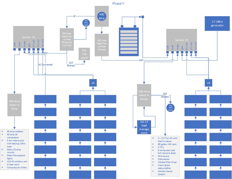
Can anyone comment on the accuracy (or inaccuracy ) of this Solark Schematic with respect to the ground locations?
I think it is inaccurate, and shows the grounds in the incorrect locations.
I understand that if I insert a fused 200A disconnect switch between grid input/meter, and it is now "first" in line , the main bonded ground will need to be removed from the current location (inside my main 200a panel). I have also been informed that every single bare copper wire in the main panel will need to be removed from the neutral shared bus bar inside the panel, and a stand alone new bus bar will need to be installed inside my main panel, and all the ground wires located there.
I will also need to remove the two ground wires (one goes to my copper pipes, the other one goes out back to two ground rods) from the main panel and relocate same into the new fused disconnect.
Lastly in my case since my grid feed enters the back of my main panel, I will need to relocate my main panel about 6 inches to the left to allow access to the grid 200A input feed, as it is against code to add any polaris lugs or wire splices of that feed inside the main panel. I cannot even just take the existing wire and run it out the side of the panel, it needs to enter a stand alone distribution box of some kind.
Schematic from latest solark manual below for comment/feedback.
Lastly, if goal is to feed the main 200a meter feed to the fused disconnect, then the transfer switch, then the solark, then back to the main panel, won't that require using 4/0 Al wire for all those connections, as anything AL smaller than that will not support 200A.
Thanks for feedback, my install is getting more complex as I learn more about NEC code.
View attachment 105895