Looks good.
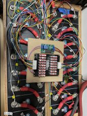
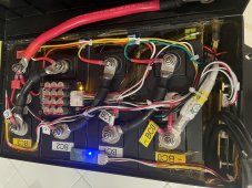
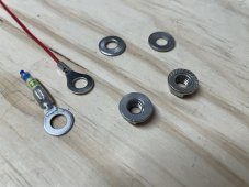
How are you achieving that amount of compression and keeping it constant? I’ve read to much compression is actually worse than no compression. Having the balance wires rings on some nuts and not on others is making the connections from cell to cell different causing different resistance and different cell voltage readings with more one wire ring on some nuts, I guess that’s why I see a lot of the solid busbars tapped (you can’t with braided flexible) so the cells nuts can all be torqued the same without having wire rings on them, so every cell is supplying the same amount of power with same resistance and same bms voltage reading for each cell.. not trying to pick apart your setup, just trying to decide out loud what’s best for me
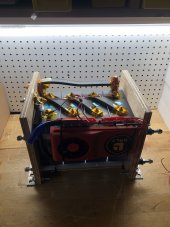
Yay! I actually saved my notes in case I wanted to build more.
Material List for:
Eight Cell Compression Module
(lithium "Squeeze Box")
Fits most 272/320 Ah Prismatic LiFePO4 cells with allowance for .045" silicone
spacers sheets on wide battery surfaces (9 places).
Home Depot 2' X 4' plywood Sheets, Radiata Pine 1/2"(.480) & 3/4"(.725) thick:
1pc Bottom 3/4" X 7" X 29-1/8"*
2pcs Sides 1/2" X 9" X 29-1/8"*
4pcs Ends 3/4" X 7"* X 8-5/16" (2per end)
2pcs Thrust plate 3/4"X 6-15/16" X 8-1/8"*
*Denotes surface grain direction. Doubled thrust plate has the only vertical grain.
Ends sit on bottom and between sides.
1 pc Spring, 634.6 LB @ .56" deflection
from MSC (mscdirect.com) PN 07661879.
1pc 3/8-16 four pronged Flange nut
1pc 3/8-16 X 3" Bolt, zinc plate (not stainless! it may bend)
1pc 3/8 fender washer, 2pcs 3/8-16 nuts
Grease for threads and washer surface.
Teks sharp point lath screws #8x1-1/4" to align while gluing.
Clamp up assembly squarely before gluing. Drill tight clearance holes through first side
and pre-drill small hole for threads.
Titebond 3 glue, re-coat edges after a few minutes soak in before assembly.
When done, protect with Minwax Helmsman Urethane 3 coats.
Sand between coats, warning very DUSTY!
"Large Silicone Heat Resistant Mat 78.7" X 15.7" (Amazon) (enough for two modules if smart).
Lightly spread a dusting of flower on sides of silicone to help it slide down between batteries,