Bud Martin
Solar Wizard
- Joined
- Aug 27, 2020
- Messages
- 4,844
"Panels are 3 in series with 6 parallel" so 18 panels total, 250W x 18 panels = 4500W of panels.8.2A per panel. Yesterday it wouldn’t have been even half that with the weather we had. Today is a better day and it is reading fine. I haven’t had an issue previously. Its because I have been trying to implement a breaker.
3s string is 8.2A, so 6 strings in parallel = 8.2A x 6 = 49.2A
The unit will only utilizing 22A max. current.
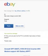
So What is the charging current you are seeing and how much power it is reporting?
You should put more panels in series to get it above startup Voltage and less parallel for less current to utilize more panel power.
Last edited: