diy solar

diy solar

My DIY 60 kW 220 panel setup

@ArkRob Sure. So the rails that the panels are attached to are 10' sections of superstrut.
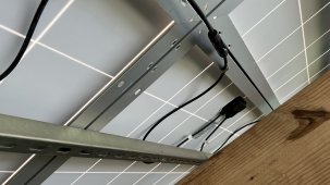
IMG_E2038.JPG

I used regular flat brackets to connect to struts together:
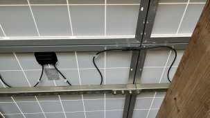
IMG_E2040.JPG

The panels are attached via cone nuts and stainless 1/4" bolts with insulated washers on the panel side:
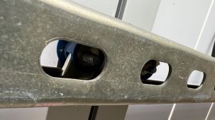
IMG_E2039.JPG

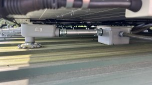
The rails of superstrut are bonded together and run into the ground on the inverters.
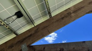
IMG_E2041.JPG

And I have East, West and South bracing on the tall side:
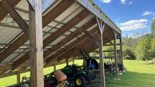
IMG_E2042.JPG

As has been pointed out earlier, I might have issues with rot at the base of the 6x6 posts being set directly in cement like they are.

I used 3/8" backer rod between the panels and siliconed the gaps as I installed the panels. I get a few drips during heavy rain, but it has held up well over the last 2 years since I installed it.

If I do any more pole barns like this, I would see if I could locate something like this to seal the gaps:
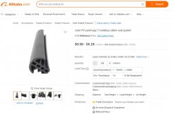
tmold.jpg

I don't need 200 meters of the stuff, which is the minimum order quantity from Alibaba. If anyone knows a good source for that molding, I'm all ears.

Let me know if you have any other questions and I'll be happy to try to answer them.
 
Last edited:
@ArkRob I used 3/8" backer rod between the panels and siliconed the gaps as I installed the panels. I get a few drips during heavy rain, but it has held up well over the last 2 years since I installed it.

If I do any more pole barns like this, I would see if I could locate something like this to seal the gaps:

View attachment 111156

I don't want 200 meters of the stuff, which is the minimum order quantity from Alibaba. If anyone knows a good source for that molding, I'm all ears.

Let me know if you have any other questions and I'll be happy to try to answer them.
Why not just use regular barn metal for a roof and use the mounts designed for that? It’s what I was planning for something similar…and then decided I don’t trust panels being on any roof in the country ($6k of mouse chewed wire damage on one my vehicles. And they are a constant battle with the other vehicles. Decided I don’t want equipment under high voltage DC).
 
The panel frames are making direct contact with the superstruts. But yeah, the NEC would probably not consider that enough. All the panels have pre-drilled holes in the frame that I could use to ground them all, but with 60 panels, that would be a huge pain. I used 1/4" stainless steel EPDM bonded sealing neoprene rubber washers to prevent a metallic reaction between the panel aluminum frame and the stainless steel. I forget where I picked up that would be a bad idea. Been a couple of years.
 
Last edited:
Why not just use regular barn metal for a roof and use the mounts designed for that? It’s what I was planning for something similar…and then decided I don’t trust panels being on any roof in the country ($6k of mouse chewed wire damage on one my vehicles. And they are a constant battle with the other vehicles. Decided I don’t want equipment under high voltage DC).

I'm cheap and didn't want the additional expense of a 22' x 48' metal roof, plus the panel hardware that I would then also have to get. furthermore, I would not have been able to get to the wiring which was a huge pain on my shop mounted panels when I was running micro inverters. Having direct access to the panel wiring like I do on my ground mount arrays, is a big plus to me.

I have been lucky and not had any issues with rodents, but I have cats that likes them, so maybe that's why. :)
 
Last edited:
I'm cheap and didn't want the additional expense of a 22' x 48' metal roof, plus the panel hardware that I would then also have to get. furthermore, I would not have been able to get to the wiring which was a huge pain on my shop mounted panels when I was running micro inverters.

I have been lucky and not had any issues with rodents, but I have cats that likes them, so maybe that's why. :)
Yeah the micro inverter part makes a lot of sense.

I was going to go with a full on equipment shed with less slope on the roof to get it a little more room to get cabbed utility size tractors or big mini exs inside and room for assorted attachments. Still might, but I am paranoid about fire.

We have lots of owls, plenty of snakes, and Boston terriers, but they don’t seem to make a dent.
 
The panel frames are making direct contact with the superstruts. But yeah, the NEC would probably not consider that enough. All the panels have pre-drilled holes in the frame that I could use to ground them all, but with 60 panels, that would be a huge pain. I used 1/4" stainless steel EPDM bonded sealing neoprene rubber washers to prevent a metallic reaction between the panel aluminum frame and the stainless steel. I forget where I picked up that would be a bad idea. Been a couple of years.
Each panel frame and the array mounts should be tied together electrically for ground.
Code requires a connector to any part that is "mechanically separate" and that means you aren't supposed to rely only on mounting bolts/clips to make the conductive connection.

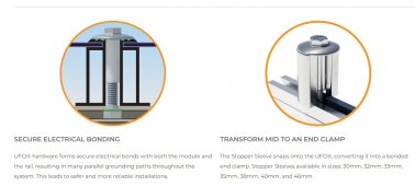
I have been using put these kind of things between the panel and rails :
 
Those are very cool clips! Not sure I can apply those after the fact since I already installed the panels. Loosing each pair of adjacent bolts and slipping one of those under the frames is going to be much more involved than just running short jumper cables between the frames. But for any future superstrut based arrays, I'll definitely do something like that.

All my regular ground mounted arrays are using Ironridge hardware and afaik, the bolts that tie the panel frames to the aluminum rails don't require additional hardware. These are what I used for those:

ironridge.jpg

I did just call in a workorder with the poco to have new 400A service installed at the shop building. Cost is $8.17 per foot regardless of 200A or 400A service. They will give me a meter base and I have to dig the trench, which is fine since I have a backhoe with a narrow 6" bucket. The run from the pole to where I want to new meter base is right around 150', so about $1,250 total, which isn't too bad.
 
If you decide to go offgrid look into used EV battery packs on ebay. Some model 3 packs can be had for <$100/kWh.
 
Diagram looks functional now. The issues and missing things I note are:
Load-shed relays where needed.
Shouldn't have more than 26 kW of SB connected to SI, while on-grid.
Is generator transfer switch instant? Or can it provide 5 seconds "off" time on output before connecting to other source?


That way, the Shop and House sub-panels are going to take what they want before any excess solar production is pushed through the SIs back into the grid, so WAY less than 54A x 4. Too bad about the communications, but since the SIs regulate the frequency and that SBs sync to that to regulate the power, I should be fine, right?

I could always kill the breakers for some of the SBs if I loose power during the middle of a bright sunny day, so not produce an excessive amount of power that I can't consume. That would keep the frequency from going too high and maybe keep everybody happier?

Frequency shift by SI will only happen when disconnected from grid. Under those conditions, SB wattage can be 2x SI wattage, according to SMA. I don't know if that is a hard limit, or depends on how fast loads are added and turned off.

When connected to grid, SB wattage is limited to 56A at 120V per SI. I don't know if export limit, implemented by Speedwire, is fast enough to comply with that. Preferable I think to limit connected SB to that number.

You could use manual interlocked breakers to move a sub panel with SB from direct on grid to on SI.
Any transfer of a grid interactive inverter (SB or SI) between two AC sources (e.g. generator/grid, or SB transfer grid/SI, must have 5 seconds "off" time, to avoid connecting out of phase while inverting.

A relay in SI can be programmed to show when on-grid. That, and possibly "generator" vs. "grid" signal, could be used to control a relay enabling/disabling the path from interlocked breakers to SI.

If I add East/West facing strings to my 7 unused MPPT inputs, you're saying I would be better off doing, say 12 facing East and 12 facing West parallel them up, and then connect to input A or B? In my current install with all 60 cell panels, I like to aim for 400V in each string to maximize efficiency.

So having 12E+12W in parallel on input A or B will be better than 12E and 12W on inputs C on 2 difference inverters?

Separate MPPT for each string will provide highest production. Paralleling two different orientation strings on one MPPT will reduce production, maybe 2% if no issues of heavily shading one string. But could save you maybe 20% in cost through higher utilization of inverter.
 
Last edited:
I just realized the 56A relay limitation in the SI is @ 120V per your comment above. So that means I would need 8 SIs to be able to backfeed 50kW plus back into the grid. And that's definitely more than I want to spend.

So yeah, let me think about how to redo the diagram to only have some power going through the SIs. Possibly just enough for what 2 SIs can handle, and then have the rest of the SBs direct grid tied.

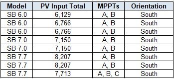
So here are the current PV capacities on my SBs:

SB capacity summary.jpg

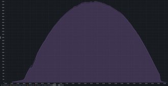
So I think adding a string of East and West facing panels to the 2 SB 7.0s, respectively, which currently have 7,150 watts going to them would be the logical next steep since those are the least over-subscribed. Here's what those 2 were doing on 9/1:

shop_roof_1_2.jpg

So they definitely have some available overhead.

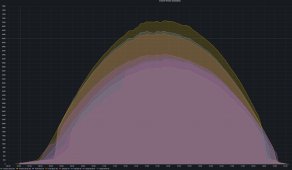
Here are all 8 SBs that day:

all_strings_9_1.jpg

So no clipping at all. While there were no clouds in the sky, it was very hot and being 9/1, it was well past the summer solstice.
 
Last edited:
Up to 4x SI can be in one cluster. Configured 2phase4 and wired 2p2s, that allows 112A pass-through, at 240V equals 26880W.
Actual voltage may push a bit higher, so higher wattage for same current limit. You can't count on perfect balance between two parallel relays (do the best you can), so that reduces wattage a bit.

I now have Midnight magnetic-hydraulic DC breakers on grid side and on island side of Sunny Islands. I measured 23A on one leg, 24A on the other.
When I first assembled it I had Square D QO270 on Island side (and Schneider 63A Multi 9 on grid side). Even with 60' total of 6 awg, the current was imbalanced about 3:1. I replaced QO with Multi 9 on island side and it was better balanced.

To have more than about 26kW or 27kW (even getting too close to that and imbalance will cause SI to open relays), on island side, they couldn't be connected and active feeding through to grid. Only connect when off grid.

To use 8x SI you would need two independent clusters. To have all 60 kW producing at the same time, 10x SI in three independent clusters.

Unless you really need a lot of power while disconnected from grid, put about 24kW of SB behind 4x SI while connected to grid. Have away to switch another 24kW onto SI after disconnecting to grid (5 second delay switching.) That's 48kW, just leave the remaining 12kW only on grid, so shut off during grid failures.

Or, with multiple orientations into 48kW of SB, you'll get the daily kWh production of 60kW single orientation, but lower peak and more hours.
I estimate with half the panels oriented SE and half SW (90 degrees between them), you can over-panel 40%, because peak output will be 70% as high as all one orientation. (It does reduce daily kWh due to longer path through air than due South.)

You only list MPPT A & B for some inverters. All those models have 3 MPPT. "A" and "B" can be paralleled, but "C" can't.
Have to consider max Imp and Isc specs to see how multiple strings might be paralleled, or how much you can over-panel with one string per MPPT.
 
Yeah, I agonized a while over how to wire the strings after removing all the micro-inverters. I did not want to pull all new wires through the conduits out to the various arrays, so I was limited by the wiring that was already in the conduits and I just reused the THHN wire already in the conduits and butt spliced in PV wire from the arrays before entering the conduits. THHN wire is rated for 600V after all.

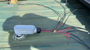
For example, this is how the PV strings on the shop roof transition into the conduit:

IMG_E1846.JPG

So that pretty much dictated the following string configurations:

SB capacity summary.jpg

I know the SBs are most efficient at around 375-400V, so I'm fairly close for most of the strings. My main concern is the 4 strings with 15 panels in series since the Talesun TP660P-270 panels in those string have a Voc of 38.5V, so 577.5V total. So if I get a really cold morning, with clear skies and low humidity, there's a small probability that I'll be over 600V when the MPPT turns on. But I think the odds are slim.

So I'm thinking I'll just leave the above string configurations the way they are and begin adding strings of 12ish panels to each vacant MPPT input, facing either East or West. I say 12ish because I don't know what panels I'm getting yet, so it will be however many will get me to about 400Vmpp.

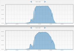
Back on Feb 27 of 2020, I had a nice cold and very clear day, and I got the following output from the 2 original SB 7.7s I had back then:

solar_clipping_Feb27_2020.PNG

As for the SIs, I'm still thinking about how to pull that off as I have some space limitation at the shop right now with where the crypto miners are located and their corresponding air cooling.

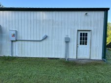
I would barely be able to fit another 400A meter base to the left of the one already there that I'm using as a junction box:

IMG_1744.JPG

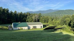
Zoomed out 8/3/22 8:09 am morning shot from when I was removing the micro inverters from the roof last month:

IMG_E1836.JPG

I'll be dropping all those pines on the left once the weather cools down some.

My loads are fairly well balanced. Past 24 hours:

line balance.jpg

A few hundred watts is looks like.
 
THHN is not sunlight resistant. Except if it is large gauge, and comes out of your meter rain head for utility drop?
Colored wires have less UV protection.
You ought to find a way to keep the sun off them.

Me, I cut MC cables in half to make pigtails, splice to THHN inside a box.


I see a recessed area at the roof penetration. Can that hold back standing water?

SI is spec'd for indoors. I put silicone sheet over controls (removed sharp metal clip from breaker, stuck square of stiffer backing sheet from silicone over the surface to let breaker handle slide.) I have it under an awning. I should also tape a flap of clear roofing material over the controls, since silicone may not hold up forever.

You can seal all cable penetrations as well so fog doesn't enter electronics compartment.

But best would be in an environment free from excess humidity.

Make sure you don't ever exceed max Voc spec, calculated using record coldest temperature. If nothing else, max voltage is logged and would invalidate warranty.
Within that limit, Ok to over-panel with higher voltage. Also higher current, not exceeding max Isc spec. But more efficient operating point would mean less heat generation, longer life.
 
I don't have any THHN exposed to the sun. That pic above was taken before the solar panel was placed over top of it. Here's a before pic when the 4 AC strings were going into it:

IMG_E1818.JPG

That's a flexible rubber boot going down through the roof. Never had a single leak since the initial install in 2016.

I buy PV cable by the 1000' reel and make my own MC cables. I had to make 80 3.5 ft. MC cables, which was a royal pain. When I removed the micros from the roof, I had about 8 MC connectors (mostly female) that I had to put new ends on since the old ones had fused/burned to the MC connectors on the micros. I went through over 200 MC connectors converting from micros to string inverters. I got really good at adding MC connectors to the end of PV wire by the end, lol.

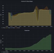
Good points about not exceeding max Voc. I plan to keep a close eye on the voltages on the array with the 15 panel strings for sure, and if I get close, I'll bypass one panel in each string with a "jumper" MC cable, during the cold months. So far I have barely kissed 500 volts a few times with temps right around 60F:

string_voltage.jpg

What is interesting is that it occurred more than an hour after the initial sun up at around 7:07 AM.

If I get the SIs they will definitely be kept indoors in the shop. Humidity can get pretty high in there during the summer, but there is little I can do about that.
 
Last edited:
Such an impressive system. If you do ever decided to do battery back up definatly go with EG4's. I'm running with 46KW of backup power installed in the server racks. The way they are setup you can connect to them via an old PC or Laptop and monitor each cell whenever you like. Thankfully though they just seem to work without any monitoring from my experiance over the last 7 months or so I've owned them.
 
Yeah, the ideal system I think would be to load up on the EG4 rack batteries and hope that the Sunny Island 8.0H will be able to communicate with it. Not in a great rush to run out and buy batteries and a charger, so I'll wait things out a bit longer to see what else comes to market. My preference would be a low frequency inverter I think since I have some pretty heavy loads.

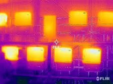
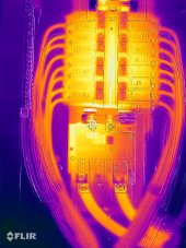
I got a new toy yesterday.

EBWR0557.JPG

Above pic is before I switched from C to F. The sub-panel in the middle top is pretty warm.

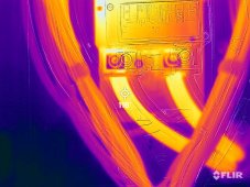
BCMP6535.JPG

Above is inside that sub-panel. 127F on the bus bar is quite hot as well. Thermal images were from yesterday around noon, so probably a bit above 200A flowing through those bus bars.

LART5311.JPG

The 300 MCM Cu was not quite as hot.
 
Yeah, the ideal system I think would be to load up on the EG4 rack batteries and hope that the Sunny Island 8.0H will be able to communicate with it. Not in a great rush to run out and buy batteries and a charger, so I'll wait things out a bit longer to see what else comes to market. My preference would be a low frequency inverter I think since I have some pretty heavy loads.

I got a new toy yesterday.

View attachment 112997

Above pic is before I switched from C to F. The sub-panel in the middle top is pretty warm.

View attachment 112999

Above is inside that sub-panel. 127F on the bus bar is quite hot as well. Thermal images were from yesterday around noon, so probably a bit above 200A flowing through those bus bars.

View attachment 113001

The 300 MCM Cu was not quite as hot.
I don’t think the EG4s communicate with SMAs. The SOK server rack rack batteries are much closer to communicating with US Sunny Islands. No idea on European versions.

Edit: Reread after fully awake. This makes more sense now lol.
 
Last edited:
Yeah, I know the EG4s won't communicate with the current gen Sunny Islands sold in the US. Hoping that the next gen ones can and/or that there will be other low frequency inverter options that can AND also regulate the output of Sunny Boys by regulating the frequency on the AC side.
 
Yeah, I know the EG4s won't communicate with the current gen Sunny Islands sold in the US. Hoping that the next gen ones can and/or that there will be other low frequency inverter options that can AND also regulate the output of Sunny Boys by regulating the frequency on the AC side.
Yeah, realized what you were saying after I looked at in a second time.
 
@crazydane Sweet setup!
Looks familiar, I think I've seen your crypto rigs on one of the crypto channels, is this correct?
 
Hello crazydane, Did you use lag bolts to attach the 10-foot long struts to the wood? Are you using 2x8 or 2x10 and are the posts 6x6? How long are the lag bolts? Any photos??? Thanks in advance for your reply
 
@BradCagle Yep, Voskcoin came out and did a couple of YouTube videos with me.

@z_zk_z Combination of lag bolts and structural brackets to attach the struts. I believe both horizontal and angled struts are 2x12s. I'll double check and also take some close up photos. Yes, the posts are 6x6s.

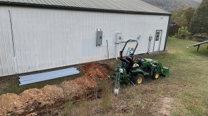
I'm currently in the process of running 400A service directly to the shop building and basically making the house a secondary building instead of the other way around. This way the shop can house the batteries, inverters, generator, etc.

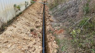
These days they make you drop conduit in the ditch instead of direct burial.

IMG_E2422.JPG

IMG_E2433.JPG

IMG_E2430.JPG

170' run from the pole to the new meter base.

IMG_E2438.JPG

They will pull 500 MCM to the meter. So instead of this:

Pole -> 200' MCM 350 -> House -> 200' MCM 500 - > Shop

It will just be:

Pole -> 170' MCM 500 -> Shop

When I'm ready, they will just move my Net meter from the old base at the house, to the new one at the shop.

My main challenge will be disconnecting and relocating the 400A disconnect and transfer switch from the house to the shop, while keeping the house powered.
 
Last edited:
I feel so inadequate now.

On a side note. There is an old paper mill up in Ponderay for sale. They have a 750 megawatt feed feed and can run over 2,000 crypto miners.
If I were you I would look into crypto mining during summer months. Be worth a whole heck of a lot more then selling back to power co.


our panels.jpg
 
Last edited:
Looking Really nice. Thanks for Sharing. I'm Guessing you've done a little electrical work before? ?
 

diy solar

diy solar
Back
Top