diy solar

diy solar

length of cable and fusing

zack6736

New Member
Joined
Jun 27, 2022
Messages
66
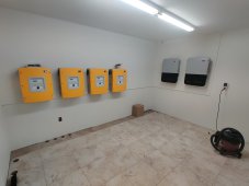
Have read the battery cable lengths must be the same on POS and NEG otherwise it effects the volts. I am installing two LV6548 inverters for two phase, all battery lengths equal but I forgot to account for a fuse (125 amp) in the POS cable from buss bar to inverter which is approx. 4" long and will have to add a short length of cable in order to use the fuse box. Questions:
1. Will this extra length on the POS cable be enough to make a difference on the volts?
2. Using a rack (5) of SOK 48v batteries each with a breaker, so is it necessary to have a fuse inline from the buss bar to inverter?
Beginner here, so taking it slow and trying to do it right.
Thank you,
zack
 
Have read the battery cable lengths must be the same on POS and NEG otherwise it effects the volts. I am installing two LV6548 inverters for two phase, all battery lengths equal but I forgot to account for a fuse (125 amp) in the POS cable from buss bar to inverter which is approx.

Nope. The total cable lengths need to be equal, e.g., #1 has (-) of 1 foot and (+) of 5 feet, #2 must have a total length of 6 feet, and (-) and (+) can vary as desired.

4" long and will have to add a short length of cable in order to use the fuse box. Questions:
1. Will this extra length on the POS cable be enough to make a difference on the volts?

If you're adding 4" to each set of cables, you're still equal.

2. Using a rack (5) of SOK 48v batteries each with a breaker, so is it necessary to have a fuse inline from the buss bar to inverter?

Isn't that where you're putting the 4" fuse?

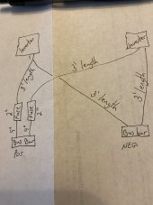
Perhaps a sketch or picture is in order.

Is also important that your AC output wires be the same length. L1 and L2 are the same length, and the two "N"s are the same length.
 
I always thought that the equal + and - cable lengths were only applicable if you have got two batteries in parallel so that you get equal charge and discharge from both batteries
 
I always thought that the equal + and - cable lengths were only applicable if you have got two batteries in parallel so that you get equal charge and discharge from both batteries

Yep, but even then, you could fudge the individual wires provided the total length of the (+) and (-) for each battery is the same.
 
Here’s a crude sketch of what I’m looking at. I have the 3’ battery cables (2/O) going from the bus bar to inverters and the fuses. I need to purchase cable to go from the bus bar to the fuse box now. I see 9” is a standard length to purchase so this would be adding another 11” to the positive cables. CF5B21A4-4189-438D-9532-AF226374D732.jpeg
 
Here’s a crude sketch of what I’m looking at. I have the 3’ battery cables (2/O) going from the bus bar to inverters and the fuses. I need to purchase cable to go from the bus bar to the fuse box now. I see 9” is a standard length to purchase so this would be adding another 11” to the positive cables.

perfectly fine. Your TOTAL length of battery wire is the same. It's not important that (+) be same as (-).

AC wires same length? Haven’t heard that before.


Section 6.7

Important with parallel inverters. Very important with parallel inverters on the same leg. They even caution against going with significantly over-sized AC wire as the reduction in resistance may contribute to imbalance. In retrospect, I was thinking these were split phase inverters. Since each inverter is its own leg, it matters very little.

@zack6736, I usually harp on this right at the beginning, but I got distracted. Your inverters are very power hungry and will likely consume about 200W 24/7. No, there isn't anything you can do about it. Low power modes are useless. Don't bother.

200W * 24h = 4800Wh

This is almost the capacity of ONE of your SOK batteries, thus it's like you only have 4 batteries. Additionally, the first 500W of your array is going to replenishing the energy the inverters consume.

If you included the 200W inverter load in your energy audit, you have nothing to worry about.
 
perfectly fine. Your TOTAL length of battery wire is the same. It's not important that (+) be same as (-).
I think I understand now. So you are talking about equal length of cable in terms of each inverter, ie, total of inverter #1 is the same as total cable length of inverter #2. Am I correct?
Also, thank you for the link to the book, this gives me some good info to read and understand more about what I'm doing.
Sucks the LV6548 sucks so much juice, but maybe down the road can upgrade to a SolArk, but not today :confused:.
 
I think I understand now. So you are talking about equal length of cable in terms of each inverter, ie, total of inverter #1 is the same as total cable length of inverter #2. Am I correct?

Yes. total (+) wiring + total (-) wiring should be equal between the two inverters, and honestly, this isn't that big of a deal as any disparity between the cable length will just manifest as additional voltage drop for the longer cables.

The most important issue is how parallel batteries are connected together and where the main terminals are placed. See 3.3 on page 17.

Also, thank you for the link to the book, this gives me some good info to read and understand more about what I'm doing.

It's wizardry I tell ya.

Sucks the LV6548 sucks so much juice, but maybe down the road can upgrade to a SolArk, but not today :confused:.

you're still ahead of the game dollar-wise. Yeah, you have to spend more on battery for the same usable capacity, but you're still notably less $/usable kWh than with a sol-ark.
 

Section 6.7

Important with parallel inverters. Very important with parallel inverters on the same leg. They even caution against going with significantly over-sized AC wire as the reduction in resistance may contribute to imbalance. In retrospect, I was thinking these were split phase inverters. Since each inverter is its own leg, it matters very little.

Well I’ll just have to live with a .00006 ohm per foot difference for my paralleled inverters that are right next to each other.
 
I'm getting ready to wire four Sunny Island 6048 inverters to a battery bank. The inverters will be in the double-split-phase configuration (240/120, two inverters per phase). At some point I had read that inverter-to-battery cable lengths (total of + and -) should be kept equal among the four inverters. The Victron booklet quoted above states this clearly:

"A large inverter/charger or a 3-phase inverter/charger can be created by connecting multiple inverter/chargers together. These units communicate with each other and, together, they become one large inverter/charger. They all need to be connected to the same battery bank. When wiring an installation like this, there are some important considerations regarding the battery cables. For correct operation it is essential that each unit receives exactly the same voltages. To ensure this the DC path from battery bank to each individual unit, or from the busbar to each individual unit needs to be exactly the same. If there is a difference between the cable thickness or the cable length between the individual units, there will be a difference between the voltages of these units. Different voltages mean different currents. The unit with a lower voltage will have a higher current running through its power electronics. Inverter/charger overload is triggered by the amount of this current. So, although the power that each inverter delivers will be the same, the unit with the lower voltage will have a larger current running through it and will go into overload before the other units do. The total inverter power of the system will now be less because when one unit goes into overload, the whole system will stop working. The unit with the bad wiring will determine the performance of the whole system. To achieve a balanced system, you will need to use the same cable type, cross-section and cable length to each unit from the battery bank or from the busbars. Also ensure that all cable lugs are identical, and all connections are tightened with the same torque values. Consider using busbars or power-posts between the battery bank and the inverter/chargers."

Now to be clear I am NOT talking about wiring multiple batteries into a single bank. I already have equal-length cables to fat bus bars to accomplish that.
But now I've re-examined the SMA Sunny Island installation manual and I can't find any mention of keeping the inverter-to-battery cables equal length; they only state that equal length is important for the AC output cabling (something Hedges has discussed extensively regarding circuit breaker resistance differentials for different brands/types of CBs).

So given the above discussion didn't seem to arrive at a definitive conclusion, can anyone shed light on this for me?

FWIW I'll be running 4/0 MTW Type K (30 AWG strands) and the shortest length I can practically make my longest inverter-to-battery run is about 22 feet (6.7m). If I don't try to make them all equal lengths, the shortest inverter-to-battery run will be about 17 feet (5.2m). Is that amount of differential (actually twice that much figuring both positive and negative will be about the same length) going to be a problem?
One alternative I have is to run a heavy (1/2" x 3" 6101 aluminum) bus bar for the negative along the distance between the inverters, so at least their negative leads will have very similar resistances to the battery bank/shunt. But to equalize the positive leads I will need to "waste" a fair amount of the expensive 4/0 wire. [Full disclosure: I already bought this wire and am concerned I somewhat underestimated the total length required, so I may not have quite enough to make all the positive wires exactly equal!:oops:] As to the aluminum bus bar, I already have that material on hand so there is little additional cost involved to use it.
 
Could be Victron's architecture and communication drives that recommendation.
Sunny Island is programmed with a voltage droop vs. current to facilitate current sharing which should tend to make it moot. (can't find the reference right now.)

Looks like SI's terminals accept up to AWG 3/0, so after some breaker/relay/etc. you'll need to transition to a smaller one from your 4/0.

I had enough 2/0 on hand to wire mine. The inverters are spaced 12" apart according to recommendations.
 
The SI terminals have an ID of 0.71", which looks like plenty of room to insert the 4/0 wire. I'll be using bootlace ferrules, as SMA recommends, but there will still be plenty of room. It won't be strictly to SMA specs, but bigger wire and fewer connections is usually a good thing.
As long as I'm violating the SMA installation specs, I also mounted them at 24" on center instead of the recommended 30-32". So there isn't 12" of free air between units, only 6". Given the design of the fan cooling arrangement and the air vents, I feel 12" is overkill. I really needed to minimize the overall wall space occupied. I'll take some temperature measurements when I have them running at full bore and see how warm the cases get.
 
Spacing probably affects convection mostly, so could increase power consumption needing fan more. Cool air comes in from the bottom, so I don't think fan cooled will be affected much (except when one blows hot air into its neighbor that doesn't have fan running.)

With most power coming from PV, SI gets to take it easy. A DC coupled system, or one powering loads from battery on a hot night, then cooling would matter more.

So I figure you can get away with it.
They will protect themselves from overheating by shutting down, and I think a signaling relay can indicate they are getting hot, could be used to shed discretionary loads.
 
Yes, as I stated, Type K stranding (2109 strands of 30 awg wire).
6000 ac watts / .85 conversion factor / 48 volts low cutoff = 147.058823529 dc amps
147.058823529 dc amps / .8 fuse headroom = 183.823529412 fuse amps

According to this calculator
4/0 awg will yield 0.68% at 44 feet round trip.

Even better with the big aluminum busbar on the return side.

I would like to see a picture of your setup including busbar when you commission the system.
 
6000 ac watts / .85 conversion factor / 48 volts low cutoff = 147.058823529 dc amps
147.058823529 dc amps / .8 fuse headroom = 183.823529412 fuse amps

5750W continuous at 25 degrees C
With AGM initially used, 42V cutoff
91% efficient at full load

5750W / 0.91 / 0.42 = 150A DC amps (very close to your figure)
150A / 0.8 = 188A fuse normally recommended.

188A * 1.12 ripple factor = 211A my fuse recommendation.

"Icy" has 250A DC breakers, sufficient for that.


Guaranteed no-trip at 100% of rating, so did not need the 80% continuous current derating.
Magnetic not thermal, so the I^R heating which drove my 112% ripple factor is not applicable. Not sure, but suspect magnetic-hydraulic simply responds to mean current.

This gets me back to 150A rating. Probably the 175A Midnight/Carlingtech breaker would have been sufficient.
But 250A should be OK. Sunny Island has its own breaker, which will protect against modest overload. Rated 10k AIC, so additional protection for battery bank is recommended. With modest AGM bank, won't exceed 10,000A short circuit current. Lithium will. The Midnight breaker is rated 50k AIC at 125VDC so is good.

Not sure exactly which Carlingtech model it is that Midnight sells. Some carry up to 135% of rating continuously.
250A x 1.35 = 338A; that is what wire would have to handle, except SI internal breaker is (something) lower. Don't know exact value.
 
Thank you @Hedges, for your in depth analysis. My calculations had arrived at a similar result, hence the Midnite Solar MNEDC250. That is a Carling Series F breaker, delay 16 (long), trip amps 313, but beyond that I'm not sure. The Carling drawing has the number FA1-B0-16-825-12A-BG. I've got a Carling spec sheet that decided the part number; it agrees with the above specs. I'll try to copy and post it's delay curve.
 
Back
Top