diy solar

diy solar

Newbie here, questions on proper grounding of DIY home system

If the only bond between battery negative and ground (which could include metal conduit or ground wires from chassis of charge controller to inverter), no way that would be substantial enough.

I have 2/0 cables from 48V 400 Ah battery positive and negative to Sunny Island inverter battery terminals.
In the event insulation on positive cable abraded through and made electrical contact to chassis of Sunny Island, current would flow from battery, through fuse, through positive cable, to inverter chassis, through (relatively small gauge) ground wire to charge controller, to (relatively small gauge) battery negative cable, back to battery.

The ground wire from charge controller to rest of ground wires is not large enough to clear the main battery fuse, and may overheat.
I think this would require a substantial ground wire from battery negative to Sunny Island chassis.

The charge controller may have GFCI, but does it actually bond PV negative to ground inside the charge controller?
And if you have several charge controllers, are PV negative bonded to ground in several places?
 
We have a large barrier island inside the city limits of Corpus Christi . the sand is 50 feet deep. when the water table gets low there is no ground at all with a grounding rod. During drouth times we go long periods of time that those grounds ground nothing. Still no damage to people or property. I can't see the need for them.
I think this is where the grounding (meaning earthing) gets confused with grounding (meaning bonding). The ground fault protection devices for roof mounted PV detect whether all the current is going through the current carrying conductors or if some of the current is leaking to the grounding (bonding) conductor. If the current is getting out of the current carrying conductors, such as if a wire rubbed through and shorted to a PV panel frame, the protection device trips so that all of the individual conductors are isolated from each other to stop the fault current and hopefully prevent a fire. All of this can happen without any current actually flowing down to the earth ground rod.

Corpus Christi is awesome, by the way. (Except for the time I visited during a red tide and the beach was covered with dead fish.)
 
The ground wire from charge controller to rest of ground wires is not large enough to clear the main battery fuse, and may overheat.
I think this would require a substantial ground wire from battery negative to Sunny Island chassis.
I was trying to ask this question. Near as I can tell, the charge controller does not protect against a short on the battery side. The fusing at the battery has to do all of that. And I did look up the NEC article on electrical storage systems, and they say that it only applies to system greater than 60 volts, so our 48 volts systems aren't subject to it.
The charge controller may have GFCI, but does it actually bond PV negative to ground inside the charge controller?
And if you have several charge controllers, are PV negative bonded to ground in several places?
I think you have to look at each charge controller as a separate electrical source in this case. In the NEC it spells out how the solar PV ground fault protection relays have to work.
Isolating Faulted Circuits
The faulted circuits shall be isolated by one of the following methods:
(1)
The current-carrying conductors of the faulted circuit
shall be automatically disconnected.
(2)
The inverter or charge controller fed by the faulted
circuit shall automatically cease to supply power to output
circuits and isolate the PV system dc circuits from the
ground reference in a functional grounded system.
So, from bullet #2, if there is a fault, even the bonded PV conductor has to be isolated from ground. So this isn't like a main panel / sub panel system. Basically, in the event of a fault, they are saying "We don't know where the fault is, so open all of the connections to the solar panel wiring."
 
The charge controller may have GFCI, but does it actually bond PV negative to ground inside the charge controller?
And if you have several charge controllers, are PV negative bonded to ground in several places?
There is a 1A (or 1/2A, I forget) fuse inside the charge controller. If the current flow between negative and ground is more than that, the fuse blows, disconnecting the circuit. If you have several charge controllers, you are supposed to disable ground fault (remove the fuse) on all the other charge controllers except the primary. Negative and ground should only be bonded in one spot.
 
Apologies hankcurt, i saw the spec sheet and thought solarqueen was talking about what i had.
The schematic I showed was for an off-grid system. It was primarily to show the connections between the charge controller and the GFP.
 
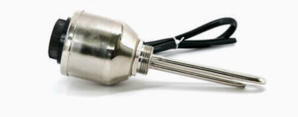
@SolarQueen, what im actually trying to do is heat water. I have a secondary tank with 2 700W 48V elements. What I have and the conf. as of now on my board i have a 150/60tr Victron CC. I have 2 baby boxes, one with an 80 amp breaker, battery side the other baby box a 30 amp on the PV side. My battery pack is 48V 200AH LiFePO4 cells. 300A Smart Ant BMS. Very close but outside mounted i have my MidNight combiner box with 3 10amp breakers. Dont have my panels yet but Thinking of Trina Soligent 310W panel and config. them 3S3P.
The Trina 310 have an Isc of 8.85A x 1.56 = 13.8A, you should have 15A breakers in the combiner box. For 3 strings, you should have 13.8 x 3 = 41A, so 50A breaker before the charge controller. Midnite Solar and Outback suggest different ways to wire the GFP. Since you have a BabyBox, you could get a 63A GFP and put it on the input of the charge controller instead of the output like Outback does. https://www.midnitesolar.com/produc...e=Breakers&productCat_ID=16&sortOrder=2&act=p See their schematic which might help, https://www.midnitesolar.com/pdfs/Kid_24V_3p_Series_REV_B.pdf
 
Okay i see , thank you for the specs. Question bout the negative and ground being bonded in one spot..... because were talking bout grounds should the bonded spot be as close as possible to the CC/battery pack?
 
Wow me and the guy i purchased this from messed up because i just confirmed i do have 10 amp breakers in my combiner and a 30 amp in my baby box before my charge controller. Great catch and thank you!! And thanks for the schematic as well! Question, is there a benefit to putting the GFP on the input of charge controller rather than the output? Gotcha on the GFP near the charge controller.
 
I trust both Outback and Midnite. They interpret the code differently from each other, so I believe either is ok. The downside to having it on the output is if you have a really big charge controller, you may not be able to get a GFP big enough. The charge controller input is usually a lower amp than output, so you can have a smaller GFP. For example, the BabyBox is DIN rail, the biggest one that is DIN rail is 63A. The 80A is panel mount. So, to use what you have, I'd have it on the input.
 
@SolarQueen, Great info and thanks so much for it! Hedges, the two heating elements i purchased have the thermostat built in at the end of the heating element. There are other designs as well meaning you can buy the desired V and W element you want then replace the original AC thermostat with DC thermostat on the tank. It has to be wired in of course, but i just purchased the because of the manufacture, design, simplicity.
 

Attachments

  • Screenshot_20201212-123020_2_Edited.png
    Screenshot_20201212-123020_2_Edited.png
    162.8 KB · Views: 5
the two heating elements i purchased have the thermostat built in at the end of the heating element.
That's good, important to have a thermostat which functions reliably with DC.
Some people here want to feed DC into an AC water heater, and I think the controls will burn out.

Be sure to have a pressure/temperature relief valve on the water tank as plumbing safety. That is your backup if the thermostat fails "on".
 
Absolutely, very important! Ive seen one video where an AC thermostat was used with DC, and If i remember correctly the guy was an electrician and he stressed it had to be EXACTLY how he done it to work but wasnt a long term deal because of AC DC differences. Im a bricklayer by trade NOT an electrician so i knew that wasnt for me! Yes i have relief valves on my tanks and they get changed bout every 5th year whether they need it or not, Ive already experienced that outcome. Ive talked to 3 people who do run these and have been for couple years and no issues so hopefully ill have the same service
 
Arc fault is for solar panels, so the charge controller takes care of that for the whole system. Likewise, the negative and ground of the PV system are protected by the GFP in the controller. No additional equipment is needed.
Are you aware of any stand-alone Arc Fault protection devices? So far I have only found devices built into other equiment (Chargers, Rapid Disconnect, Combiners)
 
Are you aware of any stand-alone Arc Fault protection devices? So far I have only found devices built into other equipment (Chargers, Rapid Disconnect, Combiners)
Sorry for the delay. I know any time I heard of someone trying to make a generic arc fault, they were getting tons of false trips. It needed to be equipment specific. I haven't found any reliable for us to carry. I haven't looked in a while though, who knows what is out there now.
 
I have a similar situation with Positive Ground related to +48vdc Commercial Telcomm Enclosure mfg. (3000 series) by Eltek for Alcatel for cell towers. I plan to reuse the enclosure for my Solar Hardware and Batteries (already wired for 3 banks of (4) 12v AGM batteries with cable harness). But originally it has a DC Rectifier chassis, smart CanBus controller, fans, heater, trouble service light, temp sensors. I am CanBus dumb and I assume it runs the environment of the box and can send alerts or alarms.

Either I strip it bare and start from scratch or remove the DC Rectifier rack and go from there retaining the DC and AC breakers. The two points of concern are that it is a Positive Ground system and the warning that states WARNING - HIGH LEAKAGE CURRENT and that proper grounding is REQUIRED. But is that due to the AC line in or the DC Rectifier chassis outputs (which will be also not be used and removed).

It basically takes inbound 208-220 single phase AC charges a DC battery bank (batteries not supplied) then powers DC Linear Rectifier equipment which has AC/48Vdc inputs (all in a climate controlled unit) to supply cell tower requirements in case of loss of line power. The system uses DIN rail mounts for the inbound and outbound breakers.
 

Attachments

  • 895CE84E-20E9-49CD-BB97-0C1857D3815D.png
    895CE84E-20E9-49CD-BB97-0C1857D3815D.png
    774.6 KB · Views: 3
I'm going to guess that "leakage" is capacitive coupling of AC to chassis. If not grounded, it would show significant AC voltage.
Equipment often has EMI filters with discrete capacitors between line and chassis, which injects a current that is related to capacitance and applied voltage.
If this box has AC into rectifiers and the output is grounded, then even if transformer isolated there is likely parasitic capacitance across the transformer and to chassis of transformer. The diodes will have capacitance.

Once you replace its charging system with your DC system (carrying PV or battery charged by SCC) I don't expect such AC coupling.
Your battery you may want negative grounded, if inverter calls for that. Positive ground tends to enhance corrosion of the negative-biased parts.
The chassis of course should be grounded, tied to rest of system which gets grounded somewhere.

AGM, if not overcharged, should be benign. At some point if cells begin to die others will be overcharged, could release hydrogen and corrosive gasses. So completely airtight and with electronics in same compartment would not be ideal. Maybe make an airtight baffle for battery and vent that? Climate controlled would help in some environments but consumes energy. AGM will produce heat when being charged, passive or fan cooling rather than sealed compartment is probably best.

Is your planned depth of cycling and number/frequency of cycles suited to AGM? Typically life is 200 to 700 cycles to 80% or proportionately more shallow cycles. I have AGM for a backup system, only cycled overnight during grid failure.
I don’t plan on using AGM batteries, what I have are LiPO4 batteries, but I do intend to make use of the AC and DC rated breakers already present and battery harnesses.

As to the mains inputs to the chassis and then inverter, I’ll have to be very certain of any bonding and grounds that may already exist within the enclosure. Like mentioned the removal of the DC Rectifier hardware may also remove other issues of a positive ground system.

All the Solar hardware is either Negative ground or Floating Ground since it not using the typical transmission line earthed AC system. The Growatt unit is 120/240 split phase with its own center tap neutral line (low frequency transformer coupled - to handle high peak starting currents 4x the normal ratings). This can be done for brief durations for appliance loads where all solid state would fry or trip continuously with the inrush startup surges.

I wish that I understood more about this smart CanBus controller an how to fully utilize it or I feel that I will loose much of the monitoring and also automation functionality already there (I will regress to manual controls and temp limit switches to run fans, relays and signal Hi/Lo, fault alerts).

As for RF/EMI the unit is definitely shielded (copper finger seals around the double gasket locking door and wirings) which if I can retain integrity will also shield the electronics from damages hopefully of EMP?

I don’t think the electronics will get to freezing or lower temperatures in Texas, the bigger issue is shading a metal box (oven) from heat and if really needed provide additional cooling. So a carport cover or block building might be an option in case of a battery fire to contain what could potentially be a run away lithium fire, although LiPO4 are supposed to be safer than you cell, laptop or AA lithium batteries.
 
That was the assumption that ERCOT made about winterizing wind turbines and natural gas supplies. That did not work out too well for the grid last year.
The included inverter generates its own heat, in a closed enclosure it would keep batteries from freezing, in Summer at 115 outside that could be a greater issue baking the contents. What you are referring to are moving parts and lubrication and stress issues like planes deal with like when ice forms on wings, not just cold alone.
 

diy solar

diy solar
Back
Top