I received the same response. It appears the GNB occurs internally when inverting from the battery. So I would assume that because I have my neutrals and grounds on the same bus and I only invert from battery as I don't have an AC IN that I do have a double GNB. But i'm still not sure if that's a problem or not.


You are using an out of date browser. It may not display this or other websites correctly.
You should upgrade or use an alternative browser.
You should upgrade or use an alternative browser.
EG4 6000EX - Double Ground/Neutral
- Thread starter HLD
- Start date
FilterGuy
Solar Engineering Consultant - EG4 and Consumers
Very interesting
One more test. No AC input, Inverter on and running from battery, what is the voltage from neutral-out to ground? If the voltage is more than a volt or so, it would indicate (nearly prove) there is no bond. If the voltage is close to zero, it is a weak indication that there is a bond.
If Sig Solar is correct, it may present a significant problem for correctly installing this inverter.
I am pretty sure that when in passthrough mode, the output transformer is acting as an auto-transformer and the mid-tap of the output transformer is providing the neutral. (The 24V between input and output neutral very strongly indicates this. If the input neutral was connected to the output neutral, the voltage would be close to zero).
When running an autotransformer, the NEC *requires* the neutral to be tied back to the neutral of the energy source. So with my model, it would look like this:

Notice that with the above layout, it is a common neutral and the NG bond in the main breaker box is 'visible' to all parts of the system.
We know that when everything is off there is no bond from neutral to ground. This is a very strong indicator that there is no dynamic bonding because on every system I know of that has dynamic bonding, the relay is in the 'bond' position when everything is off. However, on the assumption that this inverter is different, lets add the dynamic bonding to the output

Now we can see there are two NG bonds when in invert mode. One in the inverter and one in the main breaker box.
Does anyone know if there are bonding screws in this inverter?
This all indicates my model is correct.ok all potential off I have Meg ohms on output groud to neutral, Meg ohms input to output neutral and approx 24 volt neutral to ground with inverters on output line breaker off and generator input line on.
This indicates my model is incorrect.I did get a reply from SS and this is what he said. "
To answer your question about Ground neutral bonding, the units are bonded internally. The GNB location is determined by whether you have a grid or off-grid application and should be wired by your installer, as each configuration the bond will occur in a different spot before or after the inverter."
One more test. No AC input, Inverter on and running from battery, what is the voltage from neutral-out to ground? If the voltage is more than a volt or so, it would indicate (nearly prove) there is no bond. If the voltage is close to zero, it is a weak indication that there is a bond.
If Sig Solar is correct, it may present a significant problem for correctly installing this inverter.
I am pretty sure that when in passthrough mode, the output transformer is acting as an auto-transformer and the mid-tap of the output transformer is providing the neutral. (The 24V between input and output neutral very strongly indicates this. If the input neutral was connected to the output neutral, the voltage would be close to zero).
When running an autotransformer, the NEC *requires* the neutral to be tied back to the neutral of the energy source. So with my model, it would look like this:
Notice that with the above layout, it is a common neutral and the NG bond in the main breaker box is 'visible' to all parts of the system.
We know that when everything is off there is no bond from neutral to ground. This is a very strong indicator that there is no dynamic bonding because on every system I know of that has dynamic bonding, the relay is in the 'bond' position when everything is off. However, on the assumption that this inverter is different, lets add the dynamic bonding to the output
Now we can see there are two NG bonds when in invert mode. One in the inverter and one in the main breaker box.
Does anyone know if there are bonding screws in this inverter?
Yea this issue is 1 of 3 that I have, I also have a problem with power outage for 3 to 5 seconds. It happened 4 times last night with no faults or errors, my system is also switching from120v to 110v during one of those outages. I'm also dealing with them in reference to this issue.Very frustrated with all this specially being completely off grid.
FilterGuy
Solar Engineering Consultant - EG4 and Consumers
<Insert here: My long-winded angry rant about how MPP, Growatt and EG4 provide shit-poor documentation about their products>Very frustrated with all this
robby
Photon Vampire
- Joined
- May 1, 2021
- Messages
- 4,188
Honestly I don't know why you do it!<Insert here: My long-winded angry rant about how MPP, Growatt and EG4 provide shit-poor documentation about their products>
It is very clear to me that they have no interest in finding out themselves and since they don't publish it they don't have to any liability.
So they are looking for free workers on the forum to do the work so they can shift responsibility should someone get electrocuted.
sunshine_eggo
Happy Breffast!
<Insert here: My long-winded angry rant about how MPP, Growatt and EG4 provide shit-poor documentation about their products>
Going to throw Victron in there as well. Anything regulatory/code compliance - they push you to your local installer. Grounding falls squarely in this category - "refer to your local requirements."
Fortunately, with digging, one can find that with two VE.Bus inverters operating in parallel, one is configured with the GNB relay closed, and the other's relay is set to open, thus, you only have one GNB. If fed from AC input, the single GNB relay opens. If inverting, closed.
FilterGuy
Solar Engineering Consultant - EG4 and Consumers
Well, if they come after me, I have a long email trail of messages to them pointing out the issues and asking for clarifications. I will certainly try to take them down with me. (I also have an email trail with sig solar)
I have been accused of being smart, but I have never been accused of being wise....")
I have been accused of being smart, but I have never been accused of being wise....
FilterGuy
Solar Engineering Consultant - EG4 and Consumers
The local requirements can change from one town to the next town over, so I can understand and accept why a manufacturer would act as Vctron does. What is different about Victron is that you can clearly understand how their system works and someone can build safely when armed with that information. The lack of documentation is what bugs me about MPP, EG4, and Growatt. They do not provide the information needed to know what is necessary to make it safe and/or meet the code requirements. If they would just clearly state what is supported and how the product works, a competent person can figure out if it can be used in a safe way that meets the code requirments.Going to throw Victron in there as well. Anything regulatory/code compliance - they push you to your local installer. Grounding falls squarely in this category - "refer to your local requirements."
Fortunately, with digging, one can find that with two VE.Bus inverters operating in parallel, one is configured with the GNB relay closed, and the other's relay is set to open, thus, you only have one GNB. If fed from AC input, the single GNB relay opens. If inverting, closed.
sunshine_eggo
Happy Breffast!
Well, if they come after me, I have a long email trail of messages to them pointing out the issues and asking for clarifications. I will certainly try to take them down with me. (I also have an email trail with sig solar)
I have been accused of being smart, but I have never been accused of being wise....
Hmm... If "ass" comes after "wise," I hear that a lot. I'm starting to think folks may not be flattering me as much as I thought...
FilterGuy
Solar Engineering Consultant - EG4 and Consumers
We have kinda gone off into the weeds. It is fun but I would like to bring the discusion back on topic.
If someone with a unit could do the following test it would be very helpful
Conditions: Put the inverter into inverter/battery mode with no load on the output.
* No AC input,
* Inverter on and running from battery,
* no loads or other connections on the output
Test:
What is the voltage from neutral-out to ground?
Results:
* If the voltage is more than a volt or so, it would indicate (prove?) there is no bond while in inverter mode. (A bonded neutral would definitely show zero or near zero volts)
* If the voltage is close to zero, it is a weak indication that there is a bond but does not prove very much. If the neutral is bonded to ground, the voltage would zero. However, the voltage of a floating center tap could be also be zero....or it could be quite high.
ALSO: Has anyone opened a unit up? Has anyone seen neutral bonding screws?
If someone with a unit could do the following test it would be very helpful
Conditions: Put the inverter into inverter/battery mode with no load on the output.
* No AC input,
* Inverter on and running from battery,
* no loads or other connections on the output
Test:
What is the voltage from neutral-out to ground?
Results:
* If the voltage is more than a volt or so, it would indicate (prove?) there is no bond while in inverter mode. (A bonded neutral would definitely show zero or near zero volts)
(Previous tests in pass-through mode showed a 24V differential between neutral and ground. That test proved there is no bond while in passthrough mode. If there is no bond while in inverter mode and no bond in passthrough mode, then there is no dynamic bonding)
* If the voltage is close to zero, it is a weak indication that there is a bond but does not prove very much. If the neutral is bonded to ground, the voltage would zero. However, the voltage of a floating center tap could be also be zero....or it could be quite high.
ALSO: Has anyone opened a unit up? Has anyone seen neutral bonding screws?
We have kinda gone off into the weeds. It is fun but I would like to bring the discusion back on topic.
If someone with a unit could do the following test it would be very helpful
Conditions: Put the inverter into inverter/battery mode with no load on the output.
* No AC input,
* Inverter on and running from battery,
* no loads or other connections on the output
Test:
What is the voltage from neutral-out to ground?
Results:
* If the voltage is more than a volt or so, it would indicate (prove?) there is no bond while in inverter mode. (A bonded neutral would definitely show zero or near zero volts)
(Previous tests in pass-through mode showed a 24V differential between neutral and ground. That test proved there is no bond while in passthrough mode. If there is no bond while in inverter mode and no bond in passthrough mode, then there is no dynamic bonding)
* If the voltage is close to zero, it is a weak indication that there is a bond but does not prove very much. If the neutral is bonded to ground, the voltage would zero. However, the voltage of a floating center tap could be also be zero....or it could be quite high.
9
ALSO: Has anyone opened a unit up? Has anyone seen neutralI w bonding screws?
I will get on that sometime after I have my coffee this morning. As for opening that unit I can't do that due to warranty issues and since SS has not gave me permission to do so.We have kinda gone off into the weeds. It is fun but I would like to bring the discusion back on topic.
If someone with a unit could do the following test it would be very helpful
Conditions: Put the inverter into inverter/battery mode with no load on the output.
* No AC input,
* Inverter on and running from battery,
* no loads or other connections on the output
Test:
What is the voltage from neutral-out to ground?
Results:
* If the voltage is more than a volt or so, it would indicate (prove?) there is no bond while in inverter mode. (A bonded neutral would definitely show zero or near zero volts)
(Previous tests in pass-through mode showed a 24V differential between neutral and ground. That test proved there is no bond while in passthrough mode. If there is no bond while in inverter mode and no bond in passthrough mode, then there is no dynamic bonding)
* If the voltage is close to zero, it is a weak indication that there is a bond but does not prove very much. If the neutral is bonded to ground, the voltage would zero. However, the voltage of a floating center tap could be also be zero....or it could be quite high.
ALSO: Has anyone opened a unit up? Has anyone seen neutral bonding screws?
We have kinda gone off into the weeds. It is fun but I would like to bring the discusion back on topic.
If someone with a unit could do the following test it would be very helpful
Conditions: Put the inverter into inverter/battery mode with no load on the output.
* No AC input,
* Inverter on and running from battery,
* no loads or other connections on the output
Test:
What is the voltage from neutral-out to ground?
Results:
* If the voltage is more than a volt or so, it would indicate (prove?) there is no bond while in inverter mode. (A bonded neutral would definitely show zero or near zero volts)
(Previous tests in pass-through mode showed a 24V differential between neutral and ground. That test proved there is no bond while in passthrough mode. If there is no bond while in inverter mode and no bond in passthrough mode, then there is no dynamic bonding)
* If the voltage is close to zero, it is a weak indication that there is a bond but does not prove very much. If the neutral is bonded to ground, the voltage would zero. However, the voltage of a floating center tap could be also be zero....or it could be quite high.
9
ALSO: Has anyone opened a unit up? Has anyone seen neutralI w bonding screws?
We have kinda gone off into the weeds. It is fun but I would like to bring the discusion back on topic.
If someone with a unit could do the following test it would be very helpful
Conditions: Put the inverter into inverter/battery mode with no load on the output.
* No AC input,
* Inverter on and running from battery,
* no loads or other connections on the output
Test:
What is the voltage from neutral-out to ground?
Results:
* If the voltage is more than a volt or so, it would indicate (prove?) there is no bond while in inverter mode. (A bonded neutral would definitely show zero or near zero volts)
(Previous tests in pass-through mode showed a 24V differential between neutral and ground. That test proved there is no bond while in passthrough mode. If there is no bond while in inverter mode and no bond in passthrough mode, then there is no dynamic bonding)
* If the voltage is close to zero, it is a weak indication that there is a bond but does not prove very much. If the neutral is bonded to ground, the voltage would zero. However, the voltage of a floating center tap could be also be zero....or it could be quite high.
ALSO: Has anyone opened a unit up? Has anyone seen neutral
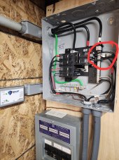
@FilterGuy When I did the test yesterday, I had to remove the NG bond on my panel(this panel is where I have both inverters output going prior to the main panel) while I was reinstalling the bond I noticed real light sparks as I was tightening the ground screw. As such I checked with my meter and did not notice any apps on it if any it was somewhere around 0.001 but the voltage was around 24 to 25volts. See pics attached. Also if you notice to the left of the panel I have a EMP Shield the led's on that unit turned off when I removed that bond it has a 3/1 connection when any 1 of those conductors are removed it won't be operational. When I do the test this morning I will have to remove that bond again and will also pay attention to that EMP Shield and see if it picks up on the so called inverter bond.
Attachments
It seems like with one Victron inverter the dynamic switching would be correct when the installation includes an AC IN and bypass mode, but with two inverters in parallel and only one switched, two ground paths would exist, one via the switched Victron bonded neutral and one via the bonded neutral at the main panel where the inverters are connected to that panel via the AC IN and the inverters are in inverter mode (not bypass).Going to throw Victron in there as well. Anything regulatory/code compliance - they push you to your local installer. Grounding falls squarely in this category - "refer to your local requirements."
Fortunately, with digging, one can find that with two VE.Bus inverters operating in parallel, one is configured with the GNB relay closed, and the other's relay is set to open, thus, you only have one GNB. If fed from AC input, the single GNB relay opens. If inverting, closed.
In short, shouldn’t both inverters switch bonding dynamically between bypass and inverter mode for a split-phase install with bypass mode?
(I saw a Will Prowse video about this issue with a split phase Victron install, but I can’t remember which one or what he said. I vaguely recall that he initially had the load center on the output side bonded or floating and hr reversed that after finding out that the Multiplex has dynamic switch, and I’m guessing he had LC bonded initially. Either way, I also recall that the install included a bypass mode AC inverter input.)
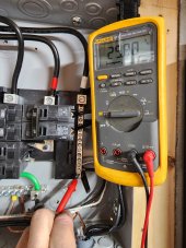
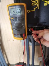
Ok I removed the NG bond in the panel output off at panel, inverters on battery/very little solar(its raining) and voltage is 31+ as shown on picture, when I reinstall the NG bond in panel I read mV. That totally odd that would mean no internal bond?.
Also my EMP Shield led turned off with my NG bond removed and back on after I reinstalled the bond.
Also my EMP Shield led turned off with my NG bond removed and back on after I reinstalled the bond.
Attachments
PreppenWolf
Solar Addict
- Joined
- Oct 10, 2022
- Messages
- 932
That means there is no bond.
FilterGuy
Solar Engineering Consultant - EG4 and Consumers
OK folks I am increasingly convinced this model of the inverter is reasonably accurate:Ok I removed the NG bond in the panel output off at panel, inverters on battery/very little solar(its raining) and voltage is 31+ as shown on picture, when I reinstall the NG bond in panel I read mV. That totally odd that would mean no internal bond?.
Also my EMP Shield led turned off with my NG bond removed and back on after I reinstalled the bond.

* The output transformer acts as an isolation transformer in inverter mode and an autotransformer in bypass mode
* The neutral is generated by the center tap in both modes
* There is no dynamic bonding
Since the NEC requires the neutral of an autotransformer be tied back to the neutral of the original power source the system should be hooked up like this:

This creates a common-neutral layout so the only bond needed in the system is the Main System Bond in the Main Breaker Box
Similar threads
- Replies
- 16
- Views
- 421
- Replies
- 6
- Views
- 174
- Replies
- 11
- Views
- 743