


You are using an out of date browser. It may not display this or other websites correctly.
You should upgrade or use an alternative browser.
You should upgrade or use an alternative browser.
EG4 6000EX - Double Ground/Neutral
- Thread starter HLD
- Start date
FilterGuy
Solar Engineering Consultant - EG4 and Consumers
Folks, in post # 49 I showed how to use a relay to dynamicly generate an NG bond for a mobil system. The original diagram was incomplete/incorrect because it did not show the NEC required connection between shore neutral and the autotransformer derived neutral.
I updated the post with this diagram:

I updated the post with this diagram:
Thanks for this and and you are correct. I was working on a diagram but yours are way better, and depict what I’m referring to.I like diagrams of what we are talking about..... because statements like that can be correct or incorrect depending on what it is refering to.
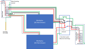
@MillAlien made a comment about needing to remove both bonds when there are multiple Victrons. I assume he was referring to a drawing like this:
View attachment 127228
In this set-up, when in pass-through, neither victron should create a bond. However, when on battery, the Victrons disconnect neutral so one and only one of the Victrons should create a bond.
I do not know if Victron supports common neutral, but assuming they do support common neutral it could be wired like this:
View attachment 127229
With this arrangement, the bond in the main breaker box is always 'visible' to all parts of the circuit. Therefor, neither Victron should ever generate a bond.
First, am I using the term “AC-bypass” correctly? Reference the diagram, I’m meaning that the Critical Load Box is fed directly from the Main Breaker Box - the AC hots are is bypassing the inverter and the neutral and ground are passing through.
(A) When the inverters are in AC-bypass both have neutral floating - the neutral-bond switches in both inverters are open and the neutrals are passed through to the Critical Load box.
(B) What I’m not understanding is the second diagram - what’s the purpose of creating a neutral bond at the inverters? Bond neutral at the battery source while using the same earth ground connection at the Main panel so that there’s still just one path the ground?
Perhaps this is confusing me because with a genset transfer switch, the neutral passes through unstitched, the genset should be floating neutral, and the only neutral bond should be at the Main panel and not at a sub panel fed by the transfer switch or at the genset (as opposed to, for example, a standalone job site generator that should have a bonded neutral and earth ground.)
FilterGuy
Solar Engineering Consultant - EG4 and Consumers
First, am I using the term “AC-bypass” correctly? Reference the diagram, I’m meaning that the Critical Load Box is fed directly from the Main Breaker Box - the AC hots are is bypassing the inverter and the neutral and ground are passing through.
Generally speaking, Bypass Mode in an inverter is when the AC input of the inverter is internally connected to the AC output of the inverter.
Battery mode or Inverter mode is when the Inverter circuit is creating the AC and putting it on the AC output and the AC input is disconnected from the AC output.
The Multiplus has a somewhat unique feature of being able to do both at the same time (Called boost mode). In Boost mode the AC input is connected to the output. The inverter is watching the current being passed through and if it exceeds a pre-configured limit it will engage the inverter circuit and battery to make up the difference between the preconfigured limit and the output current. This way if the uniti is on shore power with limited capability, the user can still get full power without tripping any breaker on the shore power.
Before Going further, I need to provide the rule for Neutral-Ground Bonds: There should always be one and only one Neutral-Ground bond in a circuit.
I am not sure what you mean by neutral floating. In this mode, the neutral is passed through from input to output and no N-G bond is created by the inverter. However neutral is not floating because of the N-G bond in the main breaker box.(A) When the inverters are in AC-bypass both have neutral floating - the neutral-bond switches in both inverters are open and the neutrals are passed through to the Critical Load box.
First: Keep in mind that this is not the way a Multiplus would normally be set up. I don't even know if Victron supports it.(B) What I’m not understanding is the second diagram - what’s the purpose of creating a neutral bond at the inverters? Bond neutral at the battery source while using the same earth ground connection at the Main panel so that there’s still just one path the ground?
I call this a common neutral layout. (The neutral is common to both the input and output) Some inverters are intended to always operate in with a common neutral. In fact some of them have the input and output permanently connected together inside the inverter. The advantage of this is that since neutral is never switched, the NG bond in the main panel is always part of the output circuit and there is no additional NG bonding in the inverter. IMHO, this is the better way to set up stationary inverters. The more complex dynamic bonding that the Multiplus does is only really needed is on a mobile installation where the N-G bond from shore power may not always be present.
Note: The Multiplus is a great inverter (one of my favorites) and they provide all the functions needed to set it up properly in a stationary environment..... but the dynamic bonding is overkill for the need)
This is always true...... except when it is not true.Perhaps this is confusing me because with a genset transfer switch, the neutral passes through unstitched, the genset should be floating neutral, and the only neutral bond should be at the Main panel and not at a sub panel fed by the transfer switch or at the genset
") Most small to medium gensets do not have an internal N-G bond. However, there are plenty of generators (particularly larger ones) that DO have an internal N-G bond. To make it even more complicated, a lot of generators that come with an internal N-G bond provide instructions on how to disconnect the N-G bond.
Most small to medium gensets do not have an internal N-G bond. However, there are plenty of generators (particularly larger ones) that DO have an internal N-G bond. To make it even more complicated, a lot of generators that come with an internal N-G bond provide instructions on how to disconnect the N-G bond.For generators without an NG-bond, the neutral should not be switched. That way the 'local' NG bond is always in the circuit.
For generators with an NG-bond, the neutral should be switched. That way the Generator NG bond is used when the generator is in the circuit and the 'local' NG-bond is in the circuit when the generator is not.
As mentioned earlier, the dynamic bonding and neutral isolation that is in many inverters is there to facilitate mobile installations where the shore power bond is there sometimes but not there other times. This is great if you need it, but adds complication if you don't need it.
Attachments
My terminology/vocabulary probably falls short here … I’m referring to what you’re referring to - no N-G bond in the inverter. In AC generators, I think this is referred to as “floating”…?I am not sure what you mean by neutral floating.
This is the crux of the biscuit…I‘ve got two Multiplus II-3000s on the way for split phse install and the reason this thread caught my attention is that the vendor (Current Connections) is reported to ship the inverters pre-configured, including the switched NGB on one inverter for inverter mode. That’s what I read anyway - I need to check w CC on this. If that wasn’t the case, then this question probably would have passed me by.First: Keep in mind that this is not the way a Multiplus would normally be set up. I don't even know if Victron supports it.
EDIT: I exchanged emails with Current Connected after the above, who told me that the Multiplus II inverters DO disconnect input neutral when in inverting mode, and I'd need one of the ground relays enabled. Consistent with this thread, they also noted that the Critical Loads panel should not an N-G bond, and added that in my application, only the earth ground is at the Main panel.
This clears this up for me since in inverter mode the Multiplus IIs disconnect both hot legs and the neutral from the AC Input and bond the AC Output neutral to ground in one of the split phase inverters, there is only one N-G Bond in that circuit - the N-G Bond at the Main panel has been disconnected from the Critical Load neutral. In AC Bypass mode however, the Multiplus disconnects its internal N-G Bond and re-connects the AC In and AC Out neutrals to re-establish the common neutral, and there again, only one N-G Bond in that circuit (at the Main panel).
The Multiplus II-3000 off-grid kit ships configured this way from Current Connected. (Among the many reasons that I purchased this kit from them and paid a little more for the Victron was to avoid DIY traps as much as possible while having super customer support).
Lessons learned are many, muchas gracias to @FilterGuy and Dexter at Current Connected.
Exactly. I was gonna qualify my statement but, … this is a real trap for the unwary DIY homeowner (e.g., me) since some generators are bonded, some aren’t, in some situations that’s ok, and in others, it’s not.This is always true...... except when it is not true.
EDIT: I suppose some transfer switches also switch the Neutrals, but not the one I have, which is why my genset can't have a N-G Bond (iow "floating neutral").
Last edited:
Hi Filter Guy,OK folks I am increasingly convinced this model of the inverter is reasonably accurate:
View attachment 127195
* The output transformer acts as an isolation transformer in inverter mode and an autotransformer in bypass mode
* The neutral is generated by the center tap in both modes
* There is no dynamic bonding
Since the NEC requires the neutral of an autotransformer be tied back to the neutral of the original power source the system should be hooked up like this:
View attachment 127198
This creates a common-neutral layout so the only bond needed in the system is the Main System Bond in the Main Breaker Box
Just saw this thread - sorry for joining this conversation late. I just installed an off grid (no AC input) EG4 6000EX and am struggling with the NG bond issue as well. I've attached my wiring diagram that's based on one of your diagrams. I'm measuring 195V between output neutral and ground! Bonding the neutral to ground at the panel causes an overcurrent surge fault in the inverter. Also measuring ground currents of 1.3A and 0.3A in two of my EGCs.
My primary load is a Juicebox EV charger or the Tesla universal mobile charger - neither charger works with the inverter and they both fault when I plug them in. I'm guessing it's because of the missing NG bond in my panel or the inverter is not internally bonded. I'm wondering if the 195V is because my ground rod is around 10 ft away from the buried copper cold water pipe that serves as the main service panel cold water pipe ground?
I previously got the Tesla charger to work (the Juicebox kept faulting) previously with a Growatt 5000, where the critical loads panel was bonded to the main service panel ground. I realize that created a double NG bond, but it was the only way I could get the Tesla charger to work. I ended up bricking the Growatt during a firmware update and replaced it with the 6000EX.
Thanks for all your reference documents that you created - very useful information. FYI, I'm a retired electrical engineering professor and a former 22 year resident of Los Gatos.
Attachments
FilterGuy
Solar Engineering Consultant - EG4 and Consumers
Wow..... 195V between output Neutral and ground is crazy!!!Hi Filter Guy,
Just saw this thread - sorry for joining this conversation late. I just installed an off grid (no AC input) EG4 6000EX and am struggling with the NG bond issue as well. I've attached my wiring diagram that's based on one of your diagrams. I'm measuring 195V between output neutral and ground! Bonding the neutral to ground at the panel causes an overcurrent surge fault in the inverter. Also measuring ground currents of 1.3A and 0.3A in two of my EGCs.
My primary load is a Juicebox EV charger or the Tesla universal mobile charger - neither charger works with the inverter and they both fault when I plug them in. I'm guessing it's because of the missing NG bond in my panel or the inverter is not internally bonded. I'm wondering if the 195V is because my ground rod is around 10 ft away from the buried copper cold water pipe that serves as the main service panel cold water pipe ground?
I previously got the Tesla charger to work (the Juicebox kept faulting) previously with a Growatt 5000, where the critical loads panel was bonded to the main service panel ground. I realize that created a double NG bond, but it was the only way I could get the Tesla charger to work. I ended up bricking the Growatt during a firmware update and replaced it with the 6000EX.
Thanks for all your reference documents that you created - very useful information. FYI, I'm a retired electrical engineering professor and a former 22 year resident of Los Gatos.
I am not sure what is causing it, but 195V kinda implies it is something from the PV circuit.

Is that ground at the panel indicating the PV negative is tied to the ground circuit? If so, disconnect that. Only the panel frames should be grounded.
Zwy
Emperor Of Solar
If the panel is bonded and the inverter is bonded, the case of the inverter and the panel can have voltage potential and be hot. This is due to the inverter having a case G to the output/input G. For the panel, the shell is bonded to G thru the bonding screw.They say you can have ground loops but I am not so convinced. If the run from the inverter to panel is short I would not worry about it.
But a single ground rod or 2 placed no more than 6/10 feet apart and firmly connected together is very important.
Thanks for the responses. Filter Guy was right - after removing the PV- to ground connection, the output neutral to ground voltage went from 195 V to a fluctuating 48 V to 55 V while the PV was connected to the inverter. The fluctuations went away and stabilized at either a constant 26.2 V or 40.5 V when the PV was disconnected. I suspect that the charger is generating a noisy waveform or there's a lot of EMI. I noticed my multimeter gave a wider range of fluctuating voltages when the meter was close to the panel wiring. This may explain why other 6000EX users are observing flickering lights. I'm also removing a ground wire between the output panel and ground bus since that was creating a ground loop (haven't done it yet). My updated wiring diagram and measurements are attached.
I did not attempt to bond my output panel NG yet, as I'm waiting to hear back from Signature Solar on the output surge code 51 fault that resulted when I bonded it a couple days ago. I did try to use my Juicebox and Tesla chargers - they both still faulted. The Tesla fault LEDs indicate a ground loss fault.
My next step is to change my ground from the dedicated ground rod to the main house ground (cold water pipe). However, I'm concerned that the 48-55 V NG voltage will drive leakage current from my off-grid system to the grid via the NG bond at the main panel.
Question 1: Can the 55 V NG voltage drive current back to the grid via the main panel bonded neutral/ground since I'm planning on using the main panel ground for my off-grid system ground?
Question 2: Since the main panel ground is a cold water pipe, doesn't the 48-55V appear on the pipe and create an electrocution hazard when using the tap or showering?
Question 3: Currently, my battery (3x LifePower4 - 48V) negative terminals are not connected to system ground. I noticed in Filter Guy's grounding guide that the batt negative terminal (BMS negative) should be grounded. I assume 10 ga wire is OK since this is to establish a common ground reference and the main battery- current is carried in my 4/0 cables from my battery bus bars to the inverter?
Attachments
FilterGuy
Solar Engineering Consultant - EG4 and Consumers
No. 55V is what one typically sees with a floating neutral. 99% of the time that is an induced voltage with almost no power behind it. As soon as the NG bond is installed it will drop to zero and my bet is that there will be nearly no detectable current between the inverter neutral and the ground.Can the 55 V NG voltage drive current back to the grid via the main panel bonded neutral/ground since I'm planning on using the main panel ground for my off-grid system ground?
Good Question.Question 3: Currently, my battery (3x LifePower4 - 48V) negative terminals are not connected to system ground. I noticed in Filter Guy's grounding guide that the batt negative terminal (BMS negative) should be grounded. I assume 10 ga wire is OK since this is to establish a common ground reference and the main battery- current is carried in my 4/0 cables from my battery bus bars to the inverter?
Strictly speaking, it is required by the NEC. However, many (most?) people don't do it.
But, wait why are my LED lights still ghostingWell I'm glad this is all clear now, lol this takes care of at least one of may issues.
But wait! Why are my LED lights ghostingWell I'm glad this is all clear now, lol this takes care of at least one of may issues.
But, wait why are my LED lights still ghosting
But wait! Why are my LED lights ghosting
Attachments
Update on my 6000EX neutral/ground and EV charging issues (see attached wiring diagram):No. 55V is what one typically sees with a floating neutral. 99% of the time that is an induced voltage with almost no power behind it. As soon as the NG bond is installed it will drop to zero and my bet is that there will be nearly no detectable current between the inverter neutral and the ground.
Good Question.
Strictly speaking, it is required by the NEC. However, many (most?) people don't do it.
a. Before adding the output neutral ground bond in my AC output panel, the neutral to ground voltage Vng = 49V to 51V. Both the Tesla Universal Mobile Charger and the Juicebox car chargers faulted.
b. Disconnected the grounding electrode conductor to the off-grid ground rod (floating ground). Bonded output panel neutral to ground. Vng = 0.01V. Both car chargers faulted. Tesla charger faults with ground loss error.
c. Connected grounding electrode conductor to both the main house panel ground AND the off-grid ground rod. Bonded output panel neutral to ground. Vng = 0.001V. The grounding electrode conductor current was 0A. Juicebox charger still faults and won't charge but the Tesla Universal Mobile Charger works but it's self limiting to 8A (used to charge at 20A with my Growatt 5000): the error notifications are: Wall plug adapter error - Charge rate reduced, charging equipment communication error, loss of connection to adapter temperature sensor. Not sure why it's throwing these errors.
Question: Now that I'm using the main service panel ground AND I had to bond the NG in my output panel to the main service ground, I have a double neutral ground bond (still don't know if the 6000EX has an internal bond or not). However, since I'm not using the AC in (no grid pass through), does the double neutral ground bond matter? I understand that if I were using the AC input from the grid, then I can't have the NG bond in my AC output panel since the main panel is the single point bond, but I'm only using the main panel ground with no AC input from the main panel. Is this a problem? Won't there be neutral current leakage from my inverter neutral to the grid neutral via the ground conductor, i.e., the off-grid system is not isolated from the grid? See attached Rev 2 wiring diagram.
Attachments
FilterGuy
Solar Engineering Consultant - EG4 and Consumers
We have never gotten a clear answer from EG4 (Or signiture solar) on this. Based on testing done by various forum members we believe that it does NOT have an internal ground. (Your results are in line with that assessment)still don't know if the 6000EX has an internal bond or not
Do you now have the grid hooked up to the input of the inverter or is the input to the inverter still unused? If the only thing hooked up between the two systems is a grounding wire, you probably do not have multiple NG bonds.Now that I'm using the main service panel ground AND I had to bond the NG in my output panel to the main service ground, I have a double neutral ground bond
It is interesting that when hooked up to just the dedicated grounding electrode both chargers faulted but when hooked up to both electrodes the Tesal started working. Have you tried just the main house grounding electrode?
Do i need a isolated ground on my system....or just wait till the battery runs low and wait on bypass to grid and the bond happens every rainny day.Other than the last two posts I don't see other posts from @parkerd on this thread so I have no context for the comments.
FilterGuy
Solar Engineering Consultant - EG4 and Consumers
I am still not understand the questions(s) I still need more context.
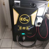
From the picture, I surmise you have an EG4 6000EX. We do not have a clear answer from EG4 or Signature Solar on whether this unit does any Neutral-Ground bonding, but based on testing done by several forum members, it appears that it does not. It appears that the center tap of the output transformer is left floating in both inverter mode and passthrough mode. This is the model I drew to represent it.

Since the output neutral is independent of the input neutral, there must be an NG bond added someplace outside of the inverter.
If the inverter is being used without the input being tied to the grid, the logical place for the NG bond would be in the breaker box that the inverter output is hooked to.

However, notice that in transfer mode, the output transformer is operating as an autotransformer. Since the NEC requires the neutral of an autotransformer to be tied back to the neutral of the originating power source, the only way this inverter model can be properly set up with the grid feeding the input is if the output neutral was connected to the grid neutral. In this case, the N-G bond in the main breaker box would always be 'seen' by the output circuits and there should NOT be another bond in the critical load box.

WARNING: EG4 has failed to properly document the grounding and bonding aspects of the 6000EX. This information is based on testing done by various forum members on the 6000EX and has not been validated by EG4.
It is rare that you would need or even want a ground on the solar system that is isolated from the rest of the building. Perhaps I am misunderstanding what 'Isolated ground' is referring to.Do i need a isolated ground on my system....
I am not sure what you mean by that.or just wait till the battery runs low and wait on bypass to grid and the bond happens every rainny day.
From the picture, I surmise you have an EG4 6000EX. We do not have a clear answer from EG4 or Signature Solar on whether this unit does any Neutral-Ground bonding, but based on testing done by several forum members, it appears that it does not. It appears that the center tap of the output transformer is left floating in both inverter mode and passthrough mode. This is the model I drew to represent it.
Since the output neutral is independent of the input neutral, there must be an NG bond added someplace outside of the inverter.
If the inverter is being used without the input being tied to the grid, the logical place for the NG bond would be in the breaker box that the inverter output is hooked to.
However, notice that in transfer mode, the output transformer is operating as an autotransformer. Since the NEC requires the neutral of an autotransformer to be tied back to the neutral of the originating power source, the only way this inverter model can be properly set up with the grid feeding the input is if the output neutral was connected to the grid neutral. In this case, the N-G bond in the main breaker box would always be 'seen' by the output circuits and there should NOT be another bond in the critical load box.
WARNING: EG4 has failed to properly document the grounding and bonding aspects of the 6000EX. This information is based on testing done by various forum members on the 6000EX and has not been validated by EG4.
OT Ducati
New Member
- Joined
- Nov 29, 2022
- Messages
- 15
When you install a transformer, you are creating a new source, you need to have a new bond.I am still not understand the questions(s) I still need more context.
It is rare that you would need or even want a ground on the solar system that is isolated from the rest of the building. Perhaps I am misunderstanding what 'Isolated ground' is referring to.
I am not sure what you mean by that.
From the picture, I surmise you have an EG4 6000EX. We do not have a clear answer from EG4 or Signature Solar on whether this unit does any Neutral-Ground bonding, but based on testing done by several forum members, it appears that it does not. It appears that the center tap of the output transformer is left floating in both inverter mode and passthrough mode. This is the model I drew to represent it.
View attachment 130022
Since the output neutral is independent of the input neutral, there must be an NG bond added someplace outside of the inverter.
If the inverter is being used without the input being tied to the grid, the logical place for the NG bond would be in the breaker box that the inverter output is hooked to.
View attachment 130027
However, notice that in transfer mode, the output transformer is operating as an autotransformer. Since the NEC requires the neutral of an autotransformer to be tied back to the neutral of the originating power source, the only way this inverter model can be properly set up with the grid feeding the input is if the output neutral was connected to the grid neutral. In this case, the N-G bond in the main breaker box would always be 'seen' by the output circuits and there should NOT be another bond in the critical load box.
View attachment 130034
WARNING: EG4 has failed to properly document the grounding and bonding aspects of the 6000EX. This information is based on testing done by various forum members on the 6000EX and has not been validated by EG4.
Yes?
FilterGuy
Solar Engineering Consultant - EG4 and Consumers
If it is an isolation transformer, then yes, the center-tap of the secondary needs to be bonded in order to make it a Grounded conductor (neutral). If the circuits are to remain isolated, that means another NG bond must be added. However, if the center tap of the 2ndary is tied back to the system neutral it can share the bond.When you install a transformer, you are creating a new source, you need to have a new bond.
Yes?
If it is an autotransformer, the NEC requires the center tap of the 2ndary be tied back to the neutral of the source. The neutral of the source will be bonded so the center tap will also be bonded.
Similar threads
- Replies
- 16
- Views
- 411
- Replies
- 5
- Views
- 151
- Replies
- 11
- Views
- 732